
Coil component

A coil component and coil technology, applied in the direction of transformer/inductor coil/winding/connection, etc., can solve problems such as inability to realize circuit functions, product failure, product open circuit, etc., to eliminate the risk of integrated inductor open circuit and solve virtual welding The problem, the effect of simple implementation

Pending Publication Date: 2022-03-25
淮安顺络文盛电子有限公司
View PDF3 Cites 2 Cited by
  • Summary
  • Abstract
  • Description
  • Claims
  • Application Information

AI Technical Summary

Problems solved by technology

If there is a paint film on the surface of the copper wire or insufficient contact between the lead wire and the metal sheet during laser welding, it may cause false welding and lead to an open circuit of the product
Due to the difference in the welding state, there may be a problem of virtual welding, which will lead to an open circuit when the product is used, and the product will fail when it is used, and the circuit function cannot be realized.

Method used


Image

  • Coil component
  • Coil component
  • Coil component

Examples


Embodiment 1

[0036] Such as Figure 1 to Figure 3 As shown, two implementations.

Embodiment approach 1

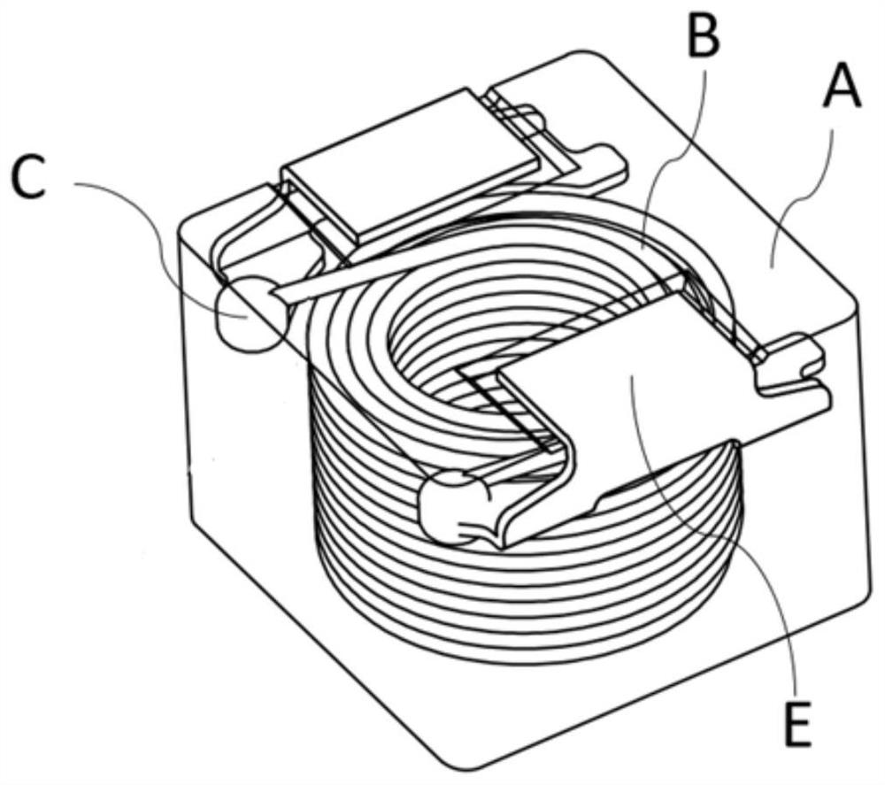
[0037] Wherein, Embodiment 1: a coil component, comprising:

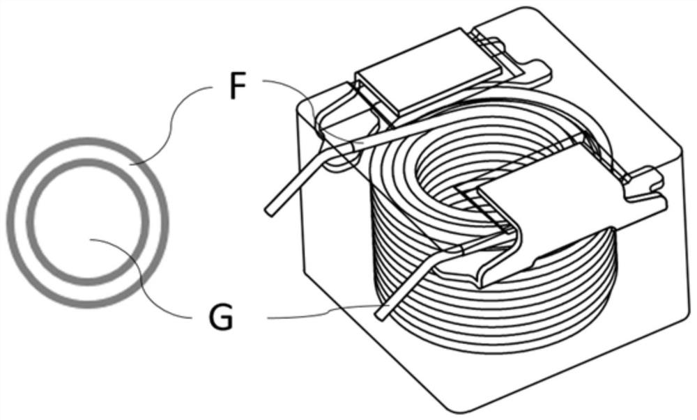
[0038] Coil B, formed by winding an enamelled copper wire 1a; it has an extended free end forming a lead-out wire 1b;

[0039] Magnet A contains soft magnetic alloy material and resin, and wraps coil B, solder joint C, and lead wire 1b inside; metal sheet E is installed on the surface of magnet A to form electrodes and connect lead wire 1b and external circuits;

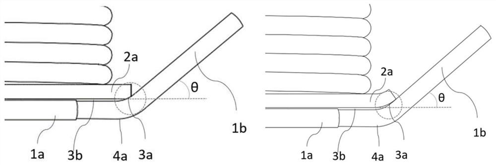
[0040] The metal sheet E is provided with protruding parts 2a at both ends of one end of the metal sheet E, and the lead-out wire 1b is bent toward the protruding part 2a near the end of the protruding part 2a, so that the lead-out wire 1b and the protruding part 2a are The ends are in contact to form a joint 3a; the surface of the magnet A is provided with a recess, and the other end of the metal sheet E is bent in the recess;

[0041] Wherein, the contact part of the lead-out line 1b and the protruding part 2a is 360° depainted, and the copper conductor...

Embodiment approach 2

[0042] Embodiment 2: A coil component, comprising:

[0043] Coil B, formed by winding an enamelled copper wire 1a; it has an extended free end forming a lead-out wire 1b;

[0044] Magnet A contains soft magnetic alloy material and resin, and wraps coil B, solder joint C, and lead wire 1b inside; metal sheet E is installed on the surface of magnet A to form electrodes and connect lead wire 1b and external circuits;

[0045] The metal sheet E is provided with protruding parts 2a at both ends of one end of the metal sheet E, and the lead-out wire 1b and the protruding part 2a are bent synchronously towards the direction of the protruding part 2a near the end of the protruding part 2a, so that the lead-out wire 1b and the protruding part 2a contact at the end position to form a joint point 3a; the surface of the magnet A is provided with a concave part, and the other end of the metal sheet E is bent in the concave part;

[0046]Wherein, the contact part of the lead wire 1b and th...


PUM


Abstract

A coil component according to the present invention comprises: a coil formed by winding an enameled copper wire; the lead-out wire is formed by an extended free end; the magnet contains a soft magnetic alloy material and resin, and wraps the coil, the welding spots and the outgoing line; a metal sheet is mounted on the surface of the magnet; protruding parts are arranged at the two ends of one end of the metal sheet, and the leading-out wires are located near the ends of the protruding parts and bent towards the protruding parts. Or the outgoing line and the protruding part are synchronously bent towards the direction of the protruding part near the end part of the protruding part; the leading-out wire is in contact with the end position of the protruding part to form a joint point, and the joint point forms a welding point after laser welding; according to the integrated inductor, no paint film is left at the welding position of the outgoing line, the outgoing line is bent according to requirements, the outgoing line is completely attached to the metal sheet in the welding process, pseudo soldering is avoided, and therefore the risk of open circuit of the integrated inductor is eliminated.

Description

technical field [0001] The invention belongs to the technical field of integrated inductors, and in particular relates to a coil component. More specifically, it relates to a connection structure between a lead wire of a coil component and a thin metal sheet. Background technique [0002] In the traditional one-piece inductor, the coil lead and the metal sheet are usually connected by laser welding. The depainted state of the copper wire at the soldering position is usually defined as no depainted or partially depainted film, and the connection method of the copper wire lead and the metal foil is not clearly defined. If there is a paint film on the surface of the copper wire or insufficient contact between the lead wire and the metal sheet during laser welding, it may cause false welding and lead to an open circuit of the product. Due to the difference in the welding state, there may be a problem of virtual welding, which will lead to an open circuit when the product is us...

Claims


Application Information

Patent Timeline
IPC IPC(8): H01F27/28H01F27/29
CPCH01F27/28H01F27/29
Inventor 苏雨波李耀光黄敬新王德明黄志胜
Owner 淮安顺络文盛电子有限公司
Learn More