Flue gas waste heat recovery system for industrial gas boiler

A flue gas waste heat and industrial gas technology, applied in preheating, water heaters, reducing greenhouse gases, etc., can solve the problems of waste heat not being fully and effectively recycled in time, energy waste, etc. Dwell time, the effect of improving the utilization rate

Active Publication Date: 2022-04-05
江西方德能源环境工程有限公司
View PDF10 Cites 2 Cited by
  • Summary
  • Abstract
  • Description
  • Claims
  • Application Information

AI Technical Summary

Problems solved by technology

[0005] In order to overcome the shortcoming that the waste heat of the industrial gas-fired boiler is not fully and effectively recycled in time when the flue gas is discharged, resulting in waste of energy, the technical problem of the present invention is: to provide a waste heat recovery method for industrial gas-fired boilers that improves the utilization rate of heat energy system

Method used


Image

  • Flue gas waste heat recovery system for industrial gas boiler
  • Flue gas waste heat recovery system for industrial gas boiler
  • Flue gas waste heat recovery system for industrial gas boiler

Examples


Embodiment 1

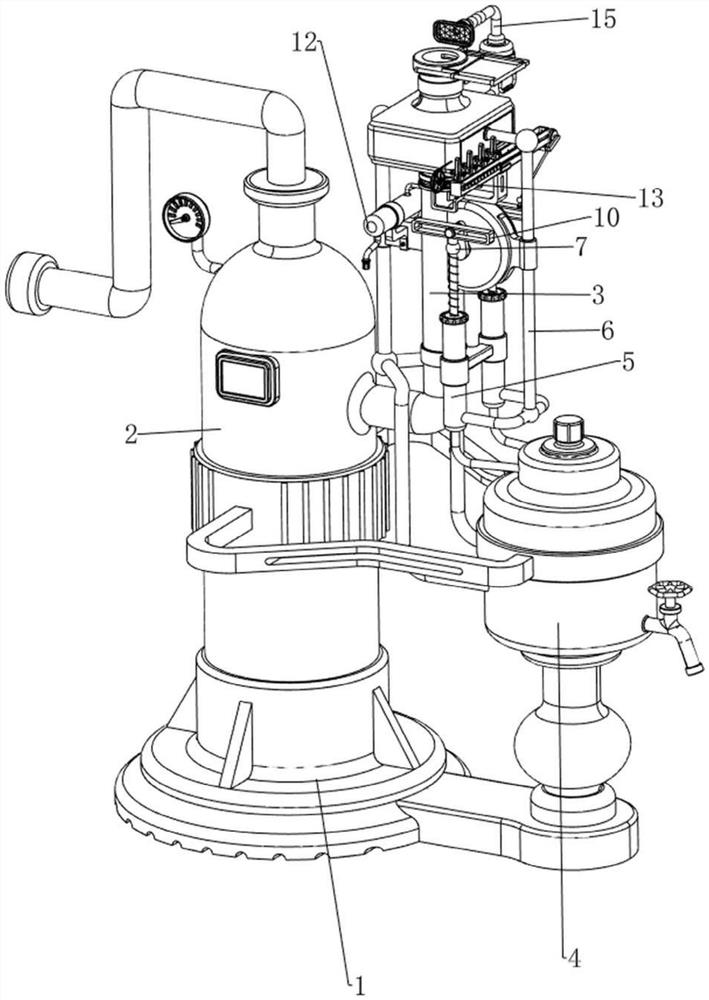
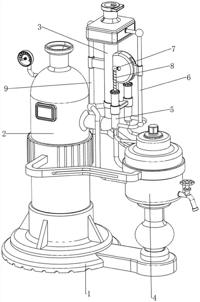
[0040] A flue gas waste heat recovery system for industrial gas boilers, such as figure 1 , figure 2 and image 3 As shown, it includes base 1, boiler 2, exhaust duct 3, economizer 4, pressurized tank 5, water inlet pipe 6, pressurized rod 7, first spring 8, return pipe 9, driving mechanism 10 and shaking mechanism 11 , the top of the base 1 is installed with a boiler 2 through bolts, the top of the boiler 2 is provided with a connecting pipe, the upper right part of the boiler 2 is fixedly provided with a flue exhaust duct 3, and the top of the exhaust duct 3 has an air outlet, and the right side of the top of the base 1 passes through The economizer 4 is installed in the form of bolts, the economizer 4 is connected with the boiler 2, the lower part of the exhaust duct 3 is connected with the economizer 4 on both sides, and there is a pressurized box 5, and the upper right part of the exhaust duct 3 is connected with the pressurized box 5 The lower part is connected with a...

Embodiment 2

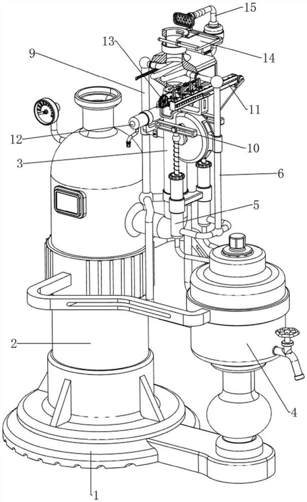
[0045] On the basis of Example 1, such as figure 1 , image 3 , Figure 9 , Figure 10 and Figure 11 As shown, a drain mechanism 12 is also included, and the drain mechanism 12 is used to collect the shaken water droplets. The drain mechanism 12 includes a water storage tank 121, a threaded cover 122, a magnetic block 123, a second torsion spring 124, and a second shift block. 125, conical block 126, scraper 127 and material receiving plate 128, the upper left part of the exhaust duct 3 is provided with a water storage tank 121, the water storage tank 121 is used to collect the water drops that shake off, and the front side of the water storage tank 121 is threaded. Threaded cover 122, the outer wall of the upper part of the exhaust duct 3 is rotatably provided with a magnetic block 123, a second torsion spring 124 is connected between the magnetic block 123 and the exhaust duct 3, and the left rear part of the slider 112 is provided with a second shifting block 125, the ...


PUM


Abstract

The invention relates to a flue gas waste heat recovery system, in particular to a flue gas waste heat recovery system for an industrial gas boiler. According to the flue gas waste heat recovery system for the industrial gas boiler, the heat energy utilization rate is increased. A flue gas waste heat recovery system for an industrial gas-fired boiler comprises a base, a boiler, a discharge flue, an energy saver, a pressurization box, a water inlet pipe, a pressurization rod and the like. A boiler is arranged on the left side of the top of the base, a discharge flue is arranged on the right upper portion of the boiler, an energy saver is arranged on the right side of the top of the base and connected with the boiler, pressurizing boxes are connected between the front side and the rear side of the lower portion of the discharge flue and the energy saver, water inlet pipes are connected between the right upper portion of the discharge flue and the lower portions of the pressurizing boxes, and pressurizing rods are arranged on the upper portions of the pressurizing boxes in a sliding mode. When the driving mechanism operates, the four first shifting blocks are driven to intermittently flap the water inlet pipe, so that water drops condensed and attached to the outer wall of the coiled pipe drop downwards, and flue gas waste heat recovery is prevented from being affected.

Description

technical field [0001] The invention relates to a flue gas waste heat recovery system, in particular to a flue gas waste heat recovery system for industrial gas boilers. Background technique [0002] Industrial gas-fired boilers are common industrial equipment that heat clean water at 15-25°C to boil and produce high-temperature steam. The fuel used is mainly gas, which consumes a lot of energy, and the problem of energy shortage has always existed. Composed of many devices, the waste heat recovery system is only a part of the industrial gas boiler system used to recover the waste heat of the flue gas. At present, the waste heat of the industrial gas boiler has not been fully and effectively recovered in time, resulting in a waste of energy. In order not to affect the industry Sustainable development, while responding to the national call for energy conservation and emission reduction, it is necessary to reasonably and efficiently recover these waste heat. [0003] Patent a...

Claims


Application Information

Patent Timeline
Patent Type & Authority Applications(China)
IPC IPC(8): F23J15/06F22D1/02
CPCY02E20/30
Inventor 姚峰张毅
Owner 江西方德能源环境工程有限公司
Why Eureka
Try Eureka