Extraction method and equipment for extracting and recycling heavy metals in electroplating sludge
A technology of electroplating sludge and extraction equipment, which is applied in the direction of chromate/dichromate, etc., can solve the problems of small footprint, and achieve the effect of small footprint, easy operation and stable operation
- Summary
- Abstract
- Description
- Claims
- Application Information
AI Technical Summary
Problems solved by technology
Method used
Image
Examples
Embodiment 1
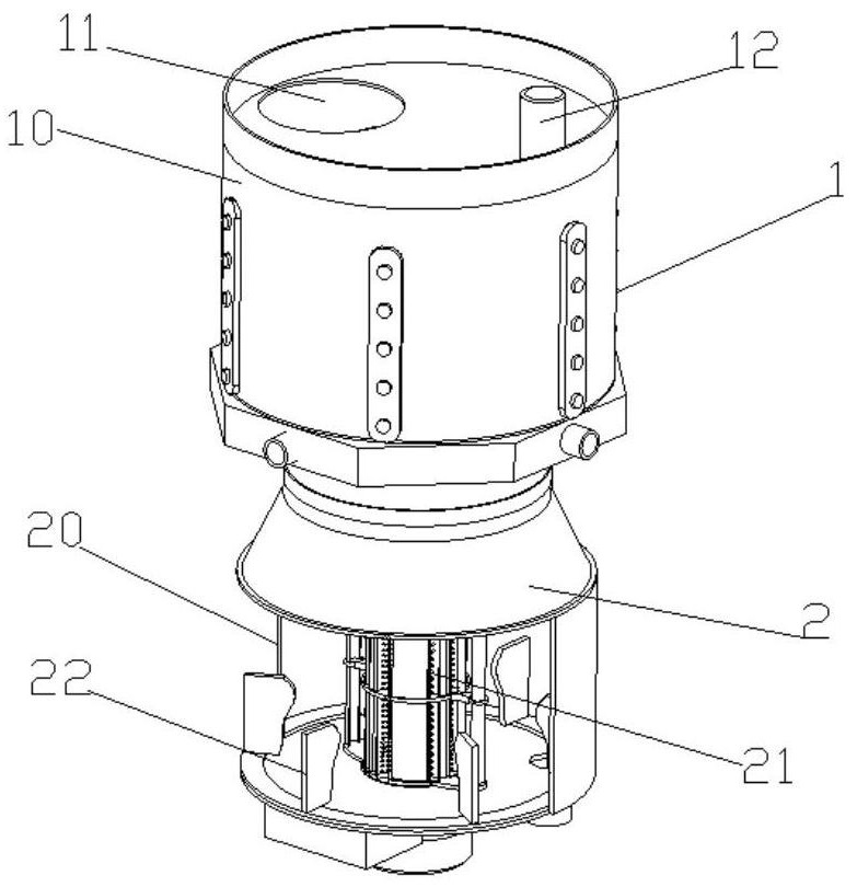
[0041] like figure 1 Shown is an extraction equipment for the extraction and recovery of heavy metals from electroplating sludge, including a first treatment device 1 for separating electroplating sludge and heavy metals, and a second treatment for step-by-step extraction of heavy metals arranged under the first treatment device 1 device 2;
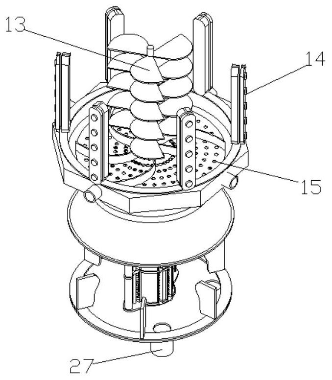
[0042] like figure 1 , 2 As shown, the first treatment device 1 includes a leaching treatment tank 10, a sludge inlet 11 arranged at the upper end of the leaching treatment tank 10, a medicine extrusion adding port 12, a mechanical agitator 13 arranged inside the leaching treatment tank 10, and a uniform ring arrangement The ultrasonic assembly 14 on the inner wall of the leaching treatment tank 10, the suction filter separator 15 arranged below the leaching treatment tank 10;
[0043] The second treatment device 2 comprises a composite extraction tank 20 connected with the suction filter separator 15, a stirring drum 21 arranged on th...
Embodiment 2
[0049] The difference with embodiment 1 is:
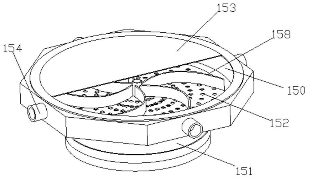
[0050] like image 3 As shown, the suction filter separator 15 includes a cylindrical separation chamber 150 arranged below the leaching treatment tank 10, and a negative pressure assembly 151 arranged below the cylindrical separation chamber 150; the connection between the lower end of the cylindrical separation chamber 150 and the negative pressure assembly 151 is provided with a A sludge interception net 152, a baffle 153 is movable at the connection between the upper end of the cylindrical separation chamber 150 and the leaching treatment tank 10; a rotating mud sweeper 158 is movable installed inside the cylindrical separation chamber 150; a mud discharge is provided on the side wall of the cylindrical separation chamber 150 Mouth 154.
[0051] like Image 6 As shown, the negative pressure assembly 151 includes a conical connecting pipe 155 connected to the first sludge intercepting net 152 at one end, a negative pressure de...
Embodiment 3
[0054] The difference with embodiment 1 is:
[0055] like figure 1 As shown, the second processing device 2 includes a composite extraction tank 20 connected to the negative pressure assembly 151, a stirring drum 21 arranged on the inner side wall of the composite extraction tank 20, and a heavy metal extraction core 22 arranged at the center of the composite extraction tank 20;
[0056] like Figure 4 , 5 As shown, the heavy metal extraction core 22 includes a mounting frame 220 arranged at the center of the composite extraction tank 20, a filter cartridge 221 arranged at the center of the mounting frame 220, an electrodeposition tank arranged on the mounting frame 220 and located at both sides of the filter cartridge 221 23. The pumping leaf fan 223 installed in the inner center of the filter cartridge 221; the upper end of the filter cartridge 221 is provided with a liquid discharge port 224 connected with the pumping leaf fan 223; the power module for driving the pumping...
PUM
 Abstract
Description
Claims
Application Information
 - R&D
- Intellectual Property
- Life Sciences
- Materials
- Tech Scout
- Unparalleled Data Quality
- Higher Quality Content
- 60% Fewer Hallucinations
Browse by: Latest US Patents, China's latest patents, Technical Efficacy Thesaurus, Application Domain, Technology Topic, Popular Technical Reports.
© 2025 PatSnap. All rights reserved.Legal|Privacy policy|Modern Slavery Act Transparency Statement|Sitemap|About US| Contact US: help@patsnap.com


