Electric vehicle charger harmonic suppression method
A harmonic suppression and electric vehicle technology, applied in electric vehicles, harmonic reduction devices, battery circuit devices, etc., can solve the problems of unrealized control and harmonic suppression, and achieve no static error tracking, reduce THD, suppress The effect of the effect of the periodic perturbation
- Summary
- Abstract
- Description
- Claims
- Application Information
AI Technical Summary
Problems solved by technology
Method used
Image
Examples
Embodiment 1
[0031] see Figure 1-Figure 5 , the method for suppressing the harmonics of the electric vehicle charger of the present invention uses a repetitive control scheme to realize the harmonic suppression of the electric vehicle charger, comprising the following steps:
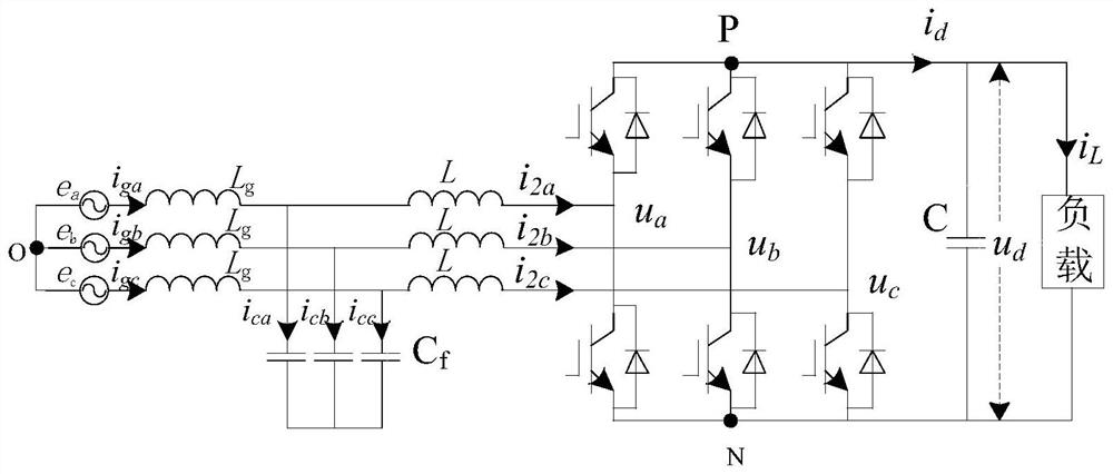
[0032] 1) Construct the topological structure of the charger with the single-phase PWM rectification method of the pre-LCL filter, such as figure 1 As shown, compared with the phase-controlled rectifier, the charger based on the PWM rectification structure has the advantages of good harmonic suppression effect and high power factor;
[0033] 2) Establish a mathematical model of a single-phase PWM rectifier charger;
[0034] 3) Analyze the harmonic characteristics in the electric vehicle charger model;
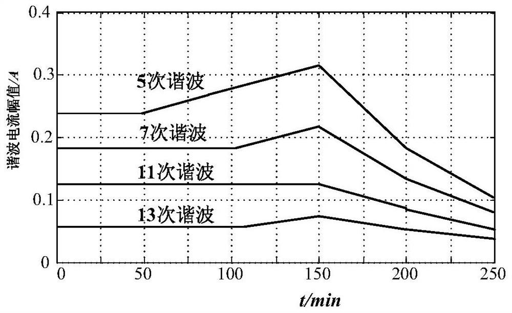
[0035] For the three-phase uncontrollable bridge-type 6-pulse rectifier charger widely used at this stage, taking the grid-side current phase A as an example, Fourier decomposition is performed, where ω is the curr...
Embodiment 2
[0045] see Figure 1-Figure 6 , the method for realizing harmonic suppression of an electric vehicle charger in this embodiment includes the following steps:
[0046] A. Construct the topological structure form of the charger with the single-phase PWM rectification method of the pre-LCL filter;
[0047] Such as figure 1 : LCL structure PWM rectifier charger topology diagram: e a , e b , e c is the three-phase power supply voltage of the grid, the inductance of the grid side and the rectifier side are L g , L, DC side current and load current are respectively i d and i L , u d is the DC side voltage, C is the DC side filter capacitor, C f It is an AC side filter capacitor, and six IGBTs form a three-phase bridge rectifier circuit. Compared with the phase-controlled rectifier, the charger based on the PWM rectification structure has the advantages of good harmonic suppression effect and high power factor.
[0048] B. Establish a mathematical model of a single-phase PWM...
PUM
 Abstract
Description
Claims
Application Information
 - R&D
- Intellectual Property
- Life Sciences
- Materials
- Tech Scout
- Unparalleled Data Quality
- Higher Quality Content
- 60% Fewer Hallucinations
Browse by: Latest US Patents, China's latest patents, Technical Efficacy Thesaurus, Application Domain, Technology Topic, Popular Technical Reports.
© 2025 PatSnap. All rights reserved.Legal|Privacy policy|Modern Slavery Act Transparency Statement|Sitemap|About US| Contact US: help@patsnap.com


