Sludge recycling device

A sludge and device frame technology, which is applied in the field of sludge recycling and utilization devices, can solve the problems of increasing the sludge recovery rate and sludge collection, and achieve the effects of increasing the recovery rate and improving the filtration speed.

Pending Publication Date: 2022-04-12
席芳芳
View PDF1 Cites 1 Cited by
  • Summary
  • Abstract
  • Description
  • Claims
  • Application Information

AI Technical Summary

Problems solved by technology

[0006] Aiming at the deficiencies of the prior art, the present invention provides a sludge recycling device, which solves the problem that the device cannot automatically collect the dehydrated sludge when recycling the sludge, and achieves the goal of automatically replacing the filter screen. The purpose is to effectively improve the filtration speed of the sludge, increase the recovery rate of the sludge, achieve the purpose of cleaning the sludge attached to the ring filter, improve the cleaning efficiency of the device, and collect the sewage in a centralized manner , which effectively improves the efficiency of sludge classification and treatment, and increases the practicability of the device

Method used


Image

  • Sludge recycling device
  • Sludge recycling device
  • Sludge recycling device

Examples


Embodiment 1

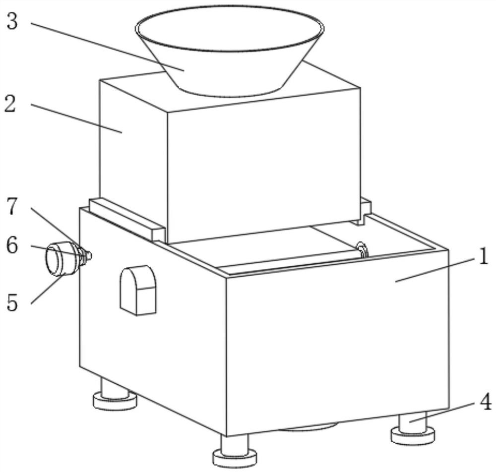
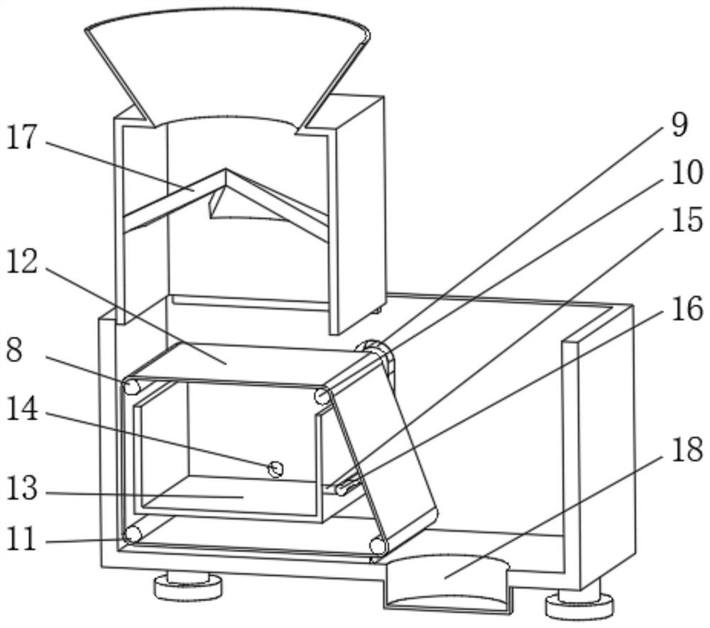
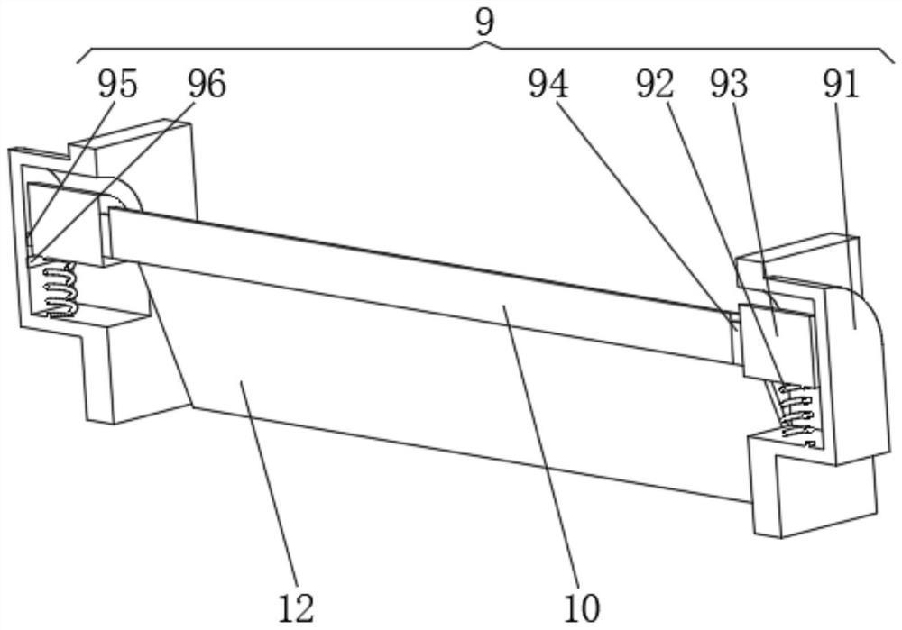
[0028] see Figure 1-3 , the present invention provides a technical solution: a sludge recycling device, including a recovery frame 1, the top of the recovery frame 1 is connected with a connection frame 2, and the side of the connection frame 2 away from the recovery frame 1 is connected with a feed pipe 3, The bottom of the recovery frame 1 is evenly equipped with a support base 4, and the outside of the recovery frame 1 is equipped with a driving motor 5, the output end of the driving motor 5 is connected to a rotating shaft 7 through a transmission 6, and the end of the rotating shaft 7 away from the transmission 6 runs through the recovery frame 1 The drive shaft 8 is connected, and the inner wall of the recovery frame 1 is connected with the control shaft 10 through the rotation of the control device 9. The inner wall of the recovery frame 1 is installed with a water collection frame 13 near the position of the drive shaft 8, and one side of the water collection frame 13 ...

Embodiment 2

[0035] see Figure 1-5 , the present invention provides a technical solution: on the basis of Embodiment 1, a scraping device 16 is installed on the end of the bracket 15 away from the water collecting frame 13, and the scraping device 16 includes a device frame 161, and the outside of the device frame 161 is connected to the bracket 15 Fixedly connected, the top of the device frame 161 is provided with a device port 162, and the inner wall of the device frame 161 is connected with a rotating column 163 through a rotating rod. An extruding block 165 is fixedly connected to the side, and an elastic airbag 166 is installed inside the device frame 161 near the extruding block 165 .

[0036] The rotating plate 164 is evenly provided with a rectangular groove 19 on the side away from the extruding block 165 , the inner wall of the rectangular groove 19 is fixedly connected with an extruding spring 20 , and the end of the extruding spring 20 away from the rectangular groove 19 is fi...


PUM


Abstract

The invention discloses a sludge recycling device which comprises a recycling frame, the top of the recycling frame communicates with a connecting frame, the side, away from the recycling frame, of the connecting frame communicates with a feeding pipe, supporting bases are evenly installed at the bottom of the recycling frame, and a driving motor is installed on the outer side of the recycling frame. The output end of the driving motor is connected with a rotating shaft through a transmission, the end, away from the transmission, of the rotating shaft penetrates through the recycling frame to be connected with a driving shaft, the inner wall of the recycling frame is rotationally connected with a control shaft through a control device, and a water collecting frame is installed at the position, close to the driving shaft, of the inner wall of the recycling frame. And one side of the water collecting frame communicates with a water outlet pipe, and conical baffles are evenly installed on the inner wall of the connecting frame. According to the sludge recycling device, dewatered sludge can be automatically collected, the purpose of automatically replacing the filter screen is achieved, and the sludge filtering speed is effectively increased.

Description

technical field [0001] The invention relates to the technical field of sludge recycling, in particular to a sludge recycling device. Background technique [0002] Sludge generated during urban life and the operation and maintenance of urban municipal facilities related to urban life activities. According to the source, it can be divided into sewage plant sludge, water supply plant sludge, drainage pipe sludge, dredging sludge and construction mud. The properties of sludge from different sources are very different, and the corresponding treatment and disposal technical requirements and resource utilization methods are also different. Sludge can be recycled, so it needs to be dewatered. [0003] For example, Chinese patent CN112010524A proposes a municipal sludge dehydration recycling device. The technical problem to be solved by the present invention is to provide a municipal sludge dehydration recycling device which can conveniently take out the dehydrated sludge and auto...

Claims


Application Information

Patent Timeline
Patent Type & Authority Applications(China)
IPC IPC(8): C02F11/123B01D29/09B01D29/60B01D29/70B01D29/94B01D29/96B01D35/12
Inventor 席芳芳
Owner 席芳芳
Why Eureka
Try Eureka