
Microprism array manufacturing method based on laser direct writing photoetching technology

A manufacturing method and laser direct writing technology, which are applied in prisms, microlithography exposure equipment, photolithography process exposure devices, etc. problems, to achieve the effect of improving performance and flexible production

Pending Publication Date: 2022-04-12
矽万(上海)半导体科技有限公司
View PDF0 Cites 0 Cited by
  • Summary
  • Abstract
  • Description
  • Claims
  • Application Information

AI Technical Summary

Problems solved by technology

The above processing methods all have certain limitations, and it is difficult to manufacture commercial microprism arrays at the micron or even nanometer level in large quantities and at low cost.
Simultaneously, the above method is also difficult to guarantee to process the microprism array with nanoscale desired size

Method used


Image

  • Microprism array manufacturing method based on laser direct writing photoetching technology
  • Microprism array manufacturing method based on laser direct writing photoetching technology

Examples


Embodiment 1

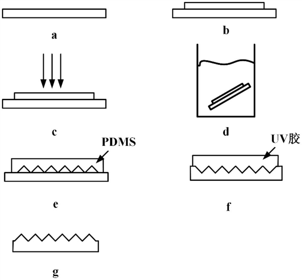
[0033] figure 1 It is a flowchart of a method for manufacturing a microprism array based on laser direct writing lithography technology according to an embodiment of the present invention. Combine below figure 1 Describe in detail. The manufacturing method of this embodiment specifically includes the following steps a-g.

[0034] Step a: Select a silicon wafer as the substrate, and clean the surface of the silicon wafer with nitrogen, such as figure 1 (a) shown.

[0035] Step b: Select a microprism array pattern with a height of 1.5 microns, spin-coat photoresist-S1818 on the silicon substrate, spin-coat at a speed of 3000rmp / min, and pre-bake for 15min, such as figure 1 In (b) shown. Specifically, this step also includes: step b1: before spin-coating the photoresist, determine the height of the photoresist according to the height of the microprisms of the desired microprism array; step b2: select the photoresist for spin coating according to the height of the photoresist...

Embodiment 2

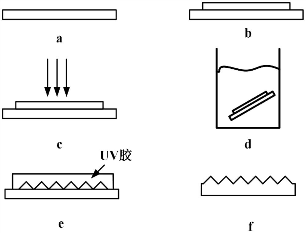
[0043] Step a: Select a silicon wafer as the substrate, and clean the surface of the silicon wafer with nitrogen, such as figure 2 (a) shown.

[0044] Step b: Select a microprism array pattern with a height of 1.5 microns, spin-coat photoresist-S1818 on the silicon substrate, spin-coat at a speed of 3000rmp / min, and pre-bake for 15min, such as figure 2 (b) shown.

[0045] Step c: Input the grayscale image of the microprism array into the laser direct writing device, select the spot size to be 200nm, the exposure dose to be 80mj / mm2, and the compensation voltage to be -1V. Then, the photoresist is exposed by laser direct writing lithography, such as figure 2 (c) shown. In this step, the input grayscale image of the microprism array is a negative grayscale image. In this embodiment, the laser is a UV laser.

[0046] Step d: Make a developer at a ratio of 3:1, and develop the exposed photoresist with the S1818 special developer, and the developing time is 5 minutes, such ...


PUM


Abstract

The invention provides a microprism array manufacturing method based on a laser direct writing photoetching technology. The microprism array manufacturing method comprises the following steps: step a, selecting a silicon wafer as a substrate; b, spin-coating photoresist on the silicon substrate, and pre-baking; c, inputting the grey-scale map of the microprism array into laser direct writing equipment, and exposing the photoresist by utilizing a laser direct writing photoetching technology; step d, developing the exposed photoresist by using a developing solution to obtain a photoresist microprism array; e, spin-coating a material on the photoresist microprism array and baking the photoresist microprism array; and f, demolding the material to obtain an expected microprism array. According to the method, the microprism array with the expected size can be effectively manufactured by using the laser direct writing photoetching technology, the production is flexible, and the product performance is greatly improved. And moreover, the photoresist is used as the transfer template, so that the product on the photoresist template can be effectively stripped, and the secondary transfer template is relatively completely stored.

Description

technical field [0001] The invention relates to the field of micro-nano manufacturing technology, in particular to a method for manufacturing a microprism array based on laser direct writing lithography technology. Background technique [0002] As a functional nano-film, microprism array is playing an increasingly important role in the fields of life, industry, and military affairs. In the LCD display industry, the problems of low luminance and uneven luminescence caused by light-emitting diodes used in backlights in liquid crystal displays can be effectively solved by using microprism arrays. For aerial photography remote cameras, the brightness and resolution of pictures can be effectively increased by introducing a microprism array into the camera. For the new Micro-LED display industry, micro-prism arrays can effectively improve the brightness of Micro-LED-based displays. [0003] At present, the processing methods for the microprism array mainly include inkjet, laser ...

Claims


Application Information

Patent Timeline
IPC IPC(8): G02B5/04G03F7/20
Inventor 栾世奕桂成群宋毅薛兆丰
Owner 矽万(上海)半导体科技有限公司
Learn More