
Fiber laser

A fiber laser and gain fiber technology, applied in the laser field, can solve the problems of low conversion efficiency of fiber oscillator, low output power of fiber laser, large numerical aperture of pump light, etc. high effect

Pending Publication Date: 2022-04-12
湖南大科激光有限公司
View PDF0 Cites 1 Cited by
  • Summary
  • Abstract
  • Description
  • Claims
  • Application Information

AI Technical Summary

Problems solved by technology

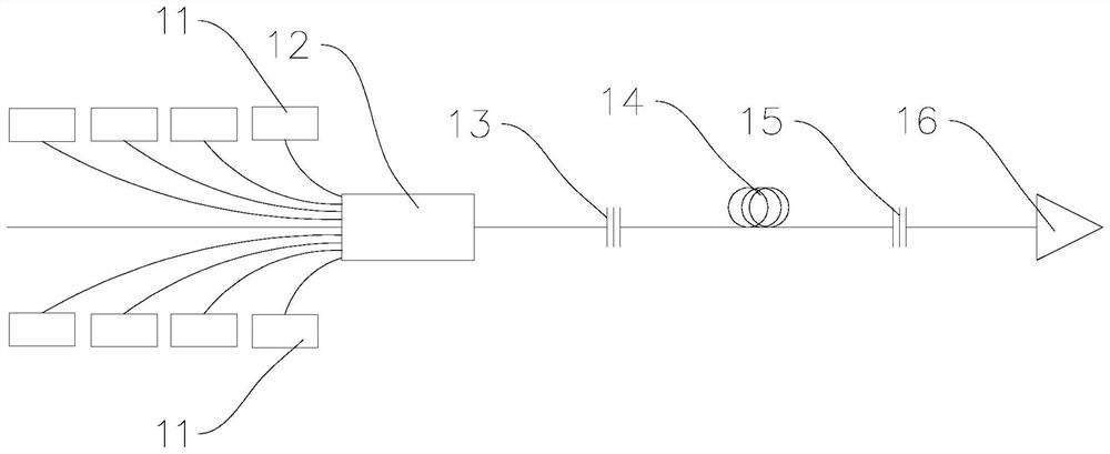
[0004] However, the numerical aperture of the pump light injected into the resonator by beam combining is relatively large, and it is difficult to be absorbed in the gain fiber 14, resulting in low conversion efficiency of the fiber oscillator and low output power of the fiber laser.
Although increasing the length of the gain fiber can improve the absorption of pump light to a certain extent, increasing the length of the gain fiber will cause the phenomenon of amplified spontaneous emission (ASE) caused by the reabsorption of the 1000nm~1030nm laser, resulting in damage to the laser

Method used


Image

  • Fiber laser
  • Fiber laser
  • Fiber laser

Examples


Embodiment Construction

[0036] The present invention will be further described below in conjunction with the accompanying drawings and embodiments.

[0037] Refer to attached figure 2 , the present embodiment provides a fiber laser, including sequentially connected pump source 21, resonant cavity, cladding optical power stripper 25 and output device 26, the resonant cavity includes grating I22, gain fiber 23 and grating II24, grating I22 One end of the pumping source 21 is coupled to the output fiber, the other end of the grating I 22 is coupled to one end of the gain fiber 23, and the other end of the gain fiber 23 is coupled to one end of the grating II 24;

[0038] Wherein, the grating I22 is a double-clad grating, and the pump source 21 is used to output pump light with a preset numerical aperture, so that the numerical aperture of the pump light entering the resonator is configured to be less than or equal to the numerical aperture of the inner cladding of the grating I22 half of. Wherein, th...


PUM

PropertyMeasurementUnit
wavelengthaaaaaaaaaa
diameteraaaaaaaaaa
reflectanceaaaaaaaaaa

Abstract

The invention relates to a fiber laser which comprises a pumping source, a resonant cavity, a cladding optical power stripper and an output device which are sequentially connected, the resonant cavity comprises a grating I, a gain fiber and a grating II, one end of the grating I is coupled with an output fiber of the pumping source, and the other end of the grating I is coupled with one end of the gain fiber; the other end of the gain fiber is coupled with one end of the grating II; wherein the grating I is a double-cladding grating, and the pumping source is used for outputting pumping light with a preset numerical aperture; or a mode field adapter is arranged between the pumping source and the resonant cavity and is used for converting the pumping light emitted by the pumping source into the pumping light with a preset numerical aperture, so that the numerical aperture of the pumping light entering the resonant cavity is configured to be less than or equal to half of the numerical aperture of the inner cladding of the grating I. The numerical aperture of the pump light entering the resonant cavity is configured to be smaller than or equal to half of the numerical aperture of the inner cladding of the grating I, so that the conversion efficiency of the optical fiber oscillator is improved.

Description

technical field [0001] The invention relates to the field of laser technology, in particular to a fiber laser. Background technique [0002] Fiber lasers have the advantages of good beam quality, high efficiency, good heat dissipation, compact structure, high reliability, and easy maintenance, and have attracted widespread attention. With the continuous expansion of the fiber laser market, the laser industry chain is becoming more and more mature, and the special processing industry has higher and higher power requirements for lasers. When the output power of a single fiber laser reaches thousands of watts, its thermal effect and nonlinear effect become the limiting factors for continued amplification. Optical fiber cascade pumping technology is an effective method to solve the problem of limited output power of a single optical fiber. Different from the traditional 976nm pumping light injected into the ytterbium-doped fiber to directly generate laser output in the 1μm ban...

Claims


Application Information

Patent Timeline
Patent Type & Authority Applications(China)
IPC IPC(8): H01S3/067H01S3/094H01S3/131
Inventor 郑文雷郭少锋徐志宏康磊
Owner 湖南大科激光有限公司
Learn More