Eureka AIR delivers breakthrough ideas for toughest innovation challenges, trusted by R&D personnel around the world.

Casting mold for metal prefabricated part

A technology of prefabricated parts and molds, which is applied in the manufacture of tools, metal processing equipment, casting molds, etc., can solve the problems of low production efficiency and long cooling cycle of sand casting, and achieve the goal of improving production efficiency, saving production costs, and accelerating cooling and forming Effect

Pending Publication Date: 2022-04-15
刘佳伟
View PDF0 Cites 0 Cited by
  • Summary
  • Abstract
  • Description
  • Claims
  • Application Information

AI Technical Summary

Problems solved by technology

[0003] Most of the existing metal prefabricated parts are made by sand casting. Firstly, the drawings of the prefabricated parts are designed, and then the models of the prefabricated parts are manufactured according to the drawings, and then the sand molds are made through the models of the prefabricated parts, and then the metal is melted And cast it into the sand mold, wait for cooling and forming, and finally get the required metal prefabricated parts after cleaning. This method has cheap and easy-to-obtain molding materials, and the casting mold is easy to manufacture. It is suitable for single-piece production, batch production and mass production of castings. It can adapt, but there are still the following disadvantages: sand casting has a long cooling cycle, and it is necessary to wait until the metal is naturally cooled and formed to open the mold to obtain prefabricated parts, resulting in low production efficiency

Method used


Image

  • Casting mold for metal prefabricated part
  • Casting mold for metal prefabricated part
  • Casting mold for metal prefabricated part

Examples


Embodiment Construction

[0035] The following will clearly and completely describe the technical solutions in the embodiments of the present invention with reference to the accompanying drawings in the embodiments of the present invention. Obviously, the described embodiments are only some, not all, embodiments of the present invention. Based on the embodiments of the present invention, all other embodiments obtained by persons of ordinary skill in the art without making creative efforts belong to the protection scope of the present invention.

[0036] In describing the present invention, it is to be understood that the terms "center", "longitudinal", "transverse", "length", "width", "thickness", "upper", "lower", "front", " Back", "Left", "Right", "Straight", "Horizontal", "Top", "Bottom", "Inner", "Outer", "Clockwise", "Counterclockwise", etc. or The positional relationship is based on the orientation or positional relationship shown in the drawings, which is only for the convenience of describing t...


PUM


Abstract

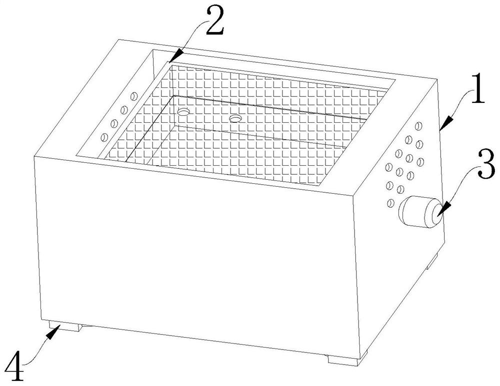
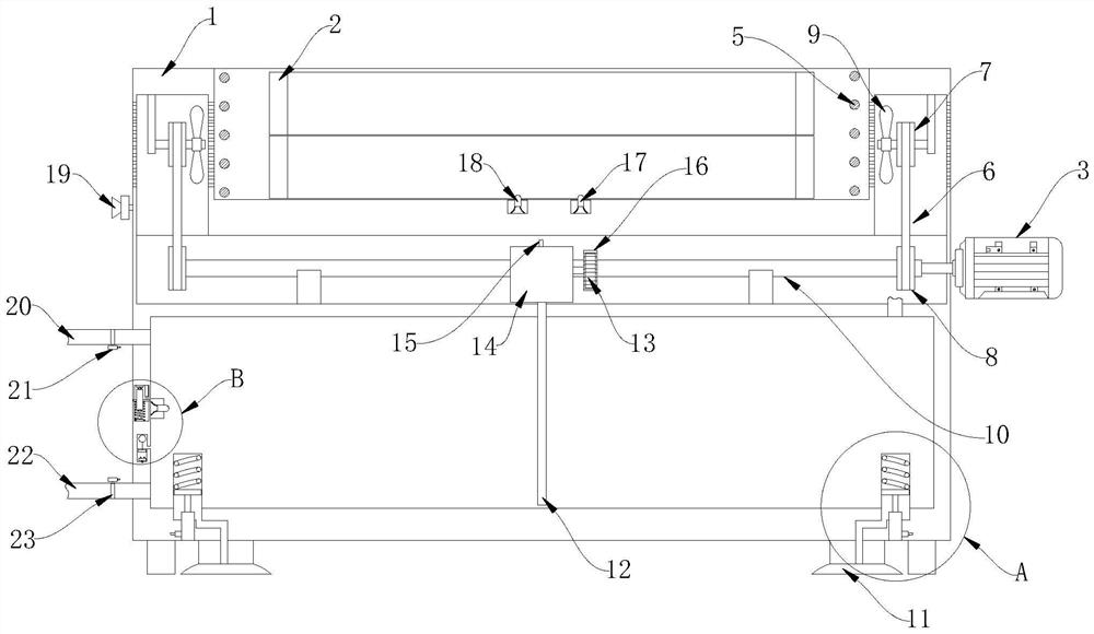
The invention relates to the technical field of prefabricated part machining, in particular to a casting mold for a metal prefabricated part. A groove is formed in the top wall of a device shell, a sand mold is movably installed in the groove, a pouring opening and an exhaust hole are formed in the sand mold, and four supporting columns are evenly and fixedly connected to the bottom end of the device shell; a water tank is arranged at the bottom end of the device shell, a water inlet pipe and a water outlet pipe are fixedly connected to one side wall of the device shell, the water inlet pipe and the water outlet pipe both communicate with the water tank, and a first electromagnetic valve is arranged on the water inlet pipe. Cooling is conducted through the condensation pipe, the pump core in the shell can guide cold water in the water tank into the condensation pipe and enable the cold water to flow in the condensation pipe, the cooling efficiency can be guaranteed, cooling forming of the metal prefabricated part can be accelerated, the production efficiency can be improved, circulation of cold air in the grooves can be accelerated in the rotating process of the fan blades, and the cooling effect is improved. And the cooling efficiency can be further improved.

Description

technical field [0001] The invention relates to the technical field of prefabricated parts processing, in particular to a casting mold for metal prefabricated parts. Background technique [0002] Casting molding, also known as (static) casting molding, is to inject the prepared casting raw materials into the mold to solidify to obtain a product similar to the mold cavity. The raw material for casting molding can be monomer, pulp after preliminary polymerization or polycondensation Polymerization or polycondensation reactions usually occur during the solidification process. In recent years, some new casting methods have appeared on the basis of traditional casting molding, including embedded casting, centrifugal casting, and flow casting. For extension casting, slush molding, rotational molding, etc., the pressure is low during casting, so the strength requirements for molds and equipment are not high, and the investment is small; the size of the product is limited, and it is...

Claims


Application Information

Patent Timeline
IPC IPC(8): B22C9/02B22D27/04
Inventor 刘佳伟李书才
Owner 刘佳伟
Why Eureka
Eureka Blog
Learn More