Processing method and equipment for silicon carbide DPF (diesel particulate filter)

A processing method and technology of processing equipment, applied in metal processing equipment, chemical instruments and methods, mechanical equipment, etc., can solve the problems of low production efficiency, difficult operation, skin and skin sticking and breaking walls, etc., to achieve high production efficiency and improve processing. Process, the effect of simplifying the processing process

Active Publication Date: 2022-04-15
岚士智能科技(上海)有限公司
View PDF6 Cites 0 Cited by
  • Summary
  • Abstract
  • Description
  • Claims
  • Application Information

AI Technical Summary

Problems solved by technology

This production method has the following problems: (1) Processing one silicon carbide DPF billet at a time, the production efficiency is low, such as mass production, it needs to invest a lot of manpower and management costs
(2) The tape should not only stick to the end face tightly to prevent the mud from entering the next-door hole during extrusion, but also protect the outer wall of the silicon carbide honeycomb ceramic from being polluted by the mud used for plugging the hole when the mud is squeezed. , the requirements for adhesive tape are high, the operation is difficult, and the product quality is easily affected due to insufficient adhesive tape
(3) In addition, when the mud material enters the channel when the hole is blocked, the water is absorbed by the hole wall, causing the strength of the silicon carbide DPF billet close to the end face to decrease. Therefore, when the tape is torn off, the skin of the fragile outer wall is glued away by the tape and broken. , resulting in product damage, the current rate of such damage exceeds 30%, affecting production efficiency

Method used


Image

  • Processing method and equipment for silicon carbide DPF (diesel particulate filter)
  • Processing method and equipment for silicon carbide DPF (diesel particulate filter)
  • Processing method and equipment for silicon carbide DPF (diesel particulate filter)

Examples


Embodiment 1

[0035] Such as figure 1 Shown, a kind of processing method of silicon carbide DPF comprises the following steps:

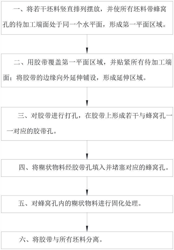
[0036] Step 1, material preparation: Arrange a number of silicon carbide DPF blanks vertically, and make the end faces of all silicon carbide DPF blanks with a number of honeycomb holes to be processed in the same horizontal plane, and cover all the end faces to be processed in the horizontal plane. The area is the first planar area.

[0037]Step 2, gluing: cover the first plane area with tape, and make the tape stick to the end faces of all silicon carbide DPF blanks to be processed; extend the edge of the tape toward the outside of the first plane area, and the vertical projection of the first plane area An extended area surrounding the first planar area is formed outside the area. Preferably, the extension area is on the same plane as the first plane area.

[0038] Step 3, punching holes: punching holes in the adhesive tape in the first plane area, and formi...

Embodiment 2

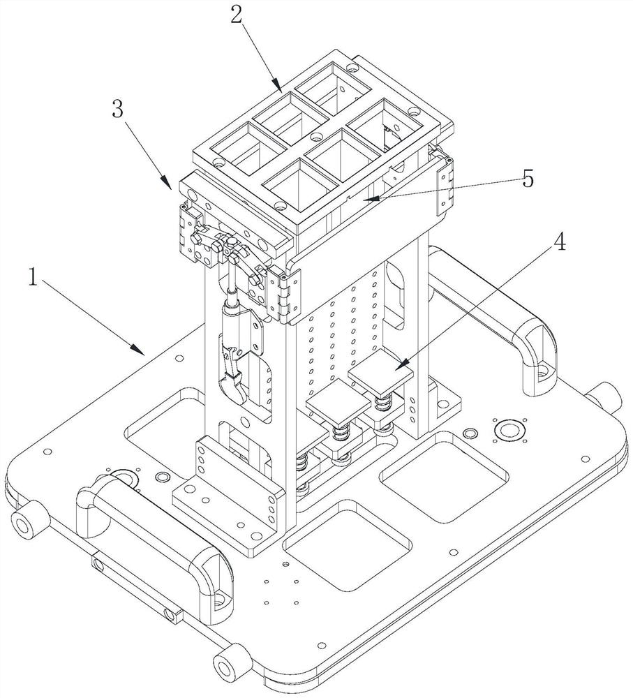
[0043] Such as Figure 1 to Figure 7 , the second embodiment provides a processing equipment for realizing the above processing method and a corresponding specific processing method. The processing equipment includes a punching machine 6 , a hole plugging machine 7 , a dryer 8 , a conveyor 9 and at least one fixture 10 . The hole puncher 6, the hole plugging machine 7 and the dryer 8 are connected in sequence by a conveyor 9. The conveyor 9 is equipped with at least one jig 10 for making the jig 10 stop the punching machine 6 , the hole plugging machine 7 and the dryer 8 in sequence.

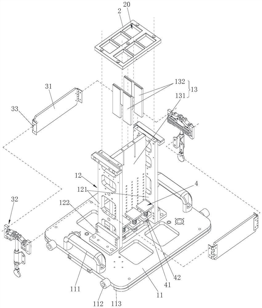
[0044] Such as Figure 2 to Figure 6 As shown, the fixture mainly includes a support base 1 , a mold frame 2 , a locking device 3 and a support block 4 . The mold frame 2 is provided with several feed holes 20 for placing the silicon carbide DPF blank a. The mold frame 2 is set on the support base 1, and the support base 1 forms a feed tank 20 at the extension of the feed hole 20, and the fe...

specific Embodiment approach

[0053] Specifically, the two splints 31 are respectively located on the front and rear sides of the main partition 131 . As a specific embodiment of the movable connection mechanism 32 : it mainly includes a sliding rail 321 , a sliding block 322 , a first connecting rod 323 , a connecting block 324 and a driving assembly 320 . The slide rail 311 is connected to the support plate 121 by means of screws or the like, and the slide rail 311 is equipped with two slide blocks 322 that can move along the slide rail 311 . Two ends of the connection block 324 are respectively hinged with a first connecting rod 323 , and the two first connecting rods 323 are respectively hinged with the two sliding blocks 322 . The connecting block 324 is equipped with a driving assembly 320 for moving the connecting block 324 up and down, and the two sliding blocks 322 are respectively connected to the two splints 31 . When the connecting block 324 moves up, the two sliding blocks 322 move closer to ...


PUM


Abstract

The invention discloses a silicon carbide DPF machining method and equipment, and belongs to the technical field of DPF machining. The method comprises the steps that S1, a plurality of silicon carbide DPF blanks are vertically arranged, and the to-be-machined end faces of all the blanks are located in a first plane area; s2, the first plane area is covered with an adhesive tape, and the edge of the adhesive tape extends outwards and is laid into an extension area; and S3, the adhesive tape above the blank is punched, blocked and cured, and then the adhesive tape is removed. Specifically, a tool clamp mainly comprising a supporting base, a mold frame, a locking device and a supporting block is adopted to achieve the step S1 and the step S2. It can be seen that multiple silicon carbide DPF blanks can be machined at the same time, efficiency is high, pasty materials for hole blocking can be prevented from entering partition honeycomb holes, the pasty materials for hole blocking are difficult to pollute the outer side walls of the blanks, the outer side walls do not need to be protected through adhesive pasting, and the problem that the outer side wall skins of the blanks are damaged due to adhesive tearing can be avoided.

Description

technical field [0001] The invention belongs to the field of workpiece clamping devices or positioning devices, and in particular relates to a processing method and equipment for a silicon carbide DPF. Background technique [0002] At present, the production of silicon carbide DPF (full name Diesel Particulate Filter, diesel particulate filter) first uses a single strip-shaped silicon carbide honeycomb ceramic blank, first loads its two ends and the outer wall with tape, and then tapes the end face. , mud plugging, mud curing, etc., and then tear off the tape. This production method has the following problems: (1) Processing one silicon carbide DPF billet at a time has low production efficiency, such as mass production, which requires a lot of manpower and management costs. (2) The tape should not only stick to the end face tightly to prevent the mud from entering the next-door hole during extrusion, but also protect the outer wall of the silicon carbide honeycomb ceramic f...

Claims


Application Information

Patent Timeline
Patent Type & Authority Applications(China)
IPC IPC(8): F01N3/022B01D46/00B05D3/02B23K26/382B28B19/00B65H37/04B65H41/00
CPCY02T10/40
Inventor 徐培锋陈振北王辉张帅李言琳
Owner 岚士智能科技(上海)有限公司
Why Eureka
Try Eureka