Manufacturing method of glass-based LED light-emitting module

A light-emitting module and manufacturing method technology, applied in the direction of electrical components, electric solid-state devices, circuits, etc., can solve the problems of alignment, flatness, high cost, and difficulty in processing Mini LED light-emitting modules, etc., to achieve Easy and precise splicing, high production efficiency, and improved alignment accuracy and alignment yield

Pending Publication Date: 2022-04-15
YANGZHOU ZHONGKE SEMICON LIGHTING
View PDF0 Cites 0 Cited by
  • Summary
  • Abstract
  • Description
  • Claims
  • Application Information

AI Technical Summary

Problems solved by technology

[0003] However, the traditional Mini LED backlight module is based on the Mini LED chip array on the PCB. Compared with the glass-based Mini LED module, the PCB-based Mini LED light-emitting module is more difficult to process, the cost is high, and the near-zero OD There are no advantages in module thickness control, large-scale processing, alignment, and flatness

Method used


Image

  • Manufacturing method of glass-based LED light-emitting module
  • Manufacturing method of glass-based LED light-emitting module
  • Manufacturing method of glass-based LED light-emitting module

Examples


Embodiment Construction

[0027] The technical solutions in the embodiments of the present invention will be clearly and completely described below in conjunction with the embodiments of the present invention. Apparently, the described embodiments are only some of the embodiments of the present invention, not all of them. Based on the embodiments of the present invention, all other embodiments obtained by persons of ordinary skill in the art without making creative efforts belong to the protection scope of the present invention.

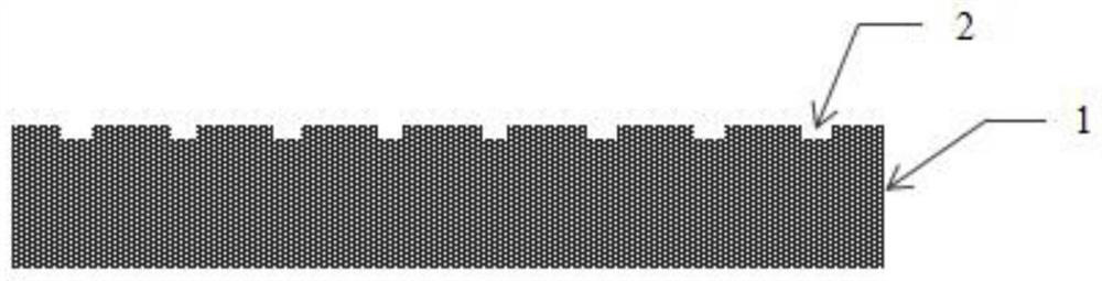
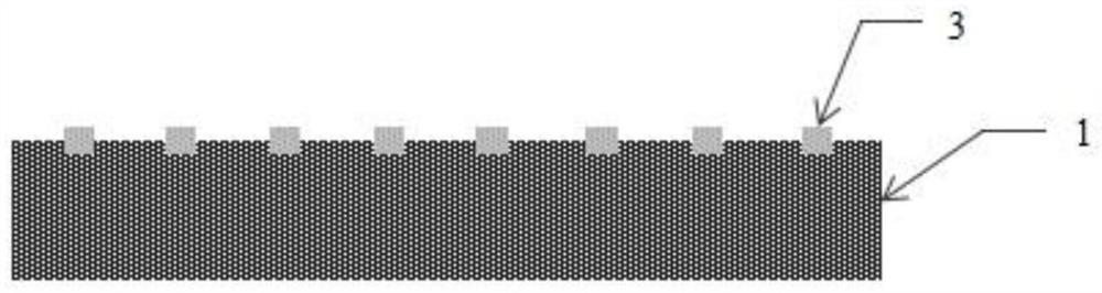
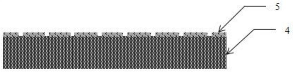
[0028] The invention discloses a method for manufacturing a glass-based LED light-emitting module. The steps include:

[0029] Step 1. Fabricate the anti-corrosion film material in the form of exposure and corrosion to form an array window structure;

[0030] Step 2. Pre-attach the film material with the arrayed window structure on one side of the glass plate 1. The size of the glass plate can be selected according to the needs. The side length of the glass plate is preferabl...


PUM

PropertyMeasurementUnit
sizeaaaaaaaaaa
depthaaaaaaaaaa
thicknessaaaaaaaaaa

Abstract

The invention discloses a manufacturing method of a glass-based LED (light-emitting diode) light-emitting module, which comprises the following steps of: performing corrosion or etching treatment on the surface of glass by taking a strong-corrosion-resistant film material as a mask to form a regular groove array structure; fixing a chip in the glass plate groove to form a glass plate provided with a high-density chip array; and aligning and attaching the glass plate provided with the conductive circuit and the glass plate of the chip array, and then carrying out laser local heating and reflow soldering treatment to form a structure that the conductive circuit glass plate, the chip and the groove array glass plate are connected into a whole. The groove array glass plate can be separated from the chip, the groove array glass plate can be repeatedly used after being cleaned, the repeatability is high, and the method is suitable for mass production. Or insulating, colorless and transparent glue is directly filled between the conductive circuit glass plate and the groove array glass plate, and a sealing structure is formed on the periphery, so that the light-emitting module is formed. And the formed light-emitting module can be subjected to double-sided thinning treatment to form the glass-based light-emitting module with the required specification.

Description

technical field [0001] The invention relates to the technical field of LED light-emitting chip modules, in particular to a method for manufacturing a glass-based LED light-emitting module. Background technique [0002] OLED display technology has fatal problems of high cost, poor reliability, and short lifespan, while Mini LED liquid crystal displays have the advantages of high peak brightness, wide color gamut, high dynamic contrast ratio (HDR), high reliability, long life, and thinness. This Mini LED direct-lit liquid crystal display backlight technology, as a new display technology with broad application prospects, is favored by the industry. The development of this technology will create an opportunity for the upgrading of the TFT-LCD display industry and boost the competition between the LCD and OLED industries. [0003] However, the traditional Mini LED backlight module is based on the Mini LED chip array on the PCB. Compared with the glass-based Mini LED module, the ...

Claims


Application Information

Patent Timeline
Patent Type & Authority Applications(China)
IPC IPC(8): H01L27/15H01L33/62
Inventor 彭寿谢义成王国宏李志聪王倩戴俊王恩平仲奕张溢高坚张应余益民
Owner YANGZHOU ZHONGKE SEMICON LIGHTING
Why Eureka
Try Eureka