Radiation imaging detector and manufacturing method thereof
A technology of radiation imaging and manufacturing method, applied in the field of radiation imaging, can solve the problem of low detection efficiency of detectors, and achieve the effects of reducing mutual interference of electrons, high resolution, and reducing signal loss
- Summary
- Abstract
- Description
- Claims
- Application Information
AI Technical Summary
Problems solved by technology
Method used
Image
Examples
Embodiment 1
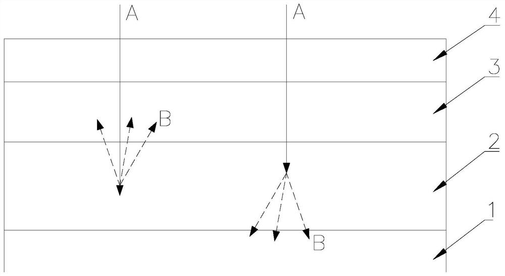
[0037] see figure 1 , figure 1 A schematic structural diagram of a radiation imaging detector provided by an embodiment of the present invention.
[0038] Such as figure 1 As shown, the first embodiment of the present invention provides a radiation imaging detector, including a sensor 1, a scintillator 2, an optical fiber composite structure 3 and an additional sensor 4, wherein the optical fiber composite structure 3 includes a plurality of optical fibers (not shown in the figure ), a sensor 1, a scintillator 2, an optical fiber composite structure 3 and an additional sensor 4 are sequentially stacked, and when a high-energy ray A (such as X-ray) is incident on the radiation imaging detector, the incident ray A generates fluorescence B through the scintillator 2, The fluorescence B on the side of the sensor 1 is directly transmitted to the sensor 1 , and the fluorescence B on the side of the additional sensor 4 is transmitted to the additional sensor 4 through the cores of ...
Embodiment 2
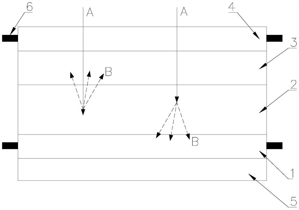
[0043] see figure 2 , figure 2 Another schematic diagram of the structure of the radiation imaging detector provided by the embodiment of the present invention.
[0044] Compared with the radiation imaging detector provided in the first embodiment of the present invention, the second embodiment of the present invention adds a substrate 5 and a data reading circuit board 6 .
[0045] Such as figure 2 As shown, the radiation imaging detector provided in this embodiment further includes a base material 5 disposed on the side of the sensor 1 away from the scintillator 2 . It should be noted that the substrate 5 is glass (such as impact-resistant alkali-free glass), and in some embodiments, the substrate 5 is flexible plastic (such as polymer organic plastic polyimide).
[0046] In this embodiment, the fiber composite structure 3 has a flat interface, incident space, and exit space. In the flat interface, incident space, and exit space of the fiber composite structure 3, ligh...
Embodiment 3
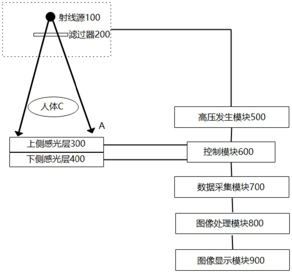
[0062] see image 3 , image 3 A schematic structural diagram of a radiation imaging detection system based on an optical fiber composite structure provided by an embodiment of the present invention.
[0063] Such as image 3 As shown, the third embodiment of the present invention provides a radiation imaging detection system based on an optical fiber composite structure, using the radiation imaging detector provided by the first embodiment and / or the second embodiment of the present invention, including a radiation source 100 , filter 200, upper side photosensitive layer 300, lower side photosensitive layer 400, high voltage generation module 500, control module 600, data acquisition module 700, image processing module 800 and image display module 900, wherein the upper side photosensitive layer 300 and The lower photosensitive layer 400 collectively represents the radiation imaging detector provided in the first embodiment and / or the second embodiment of the present invent...
PUM
| Property | Measurement | Unit |
|---|---|---|
| diameter | aaaaa | aaaaa |
| thickness | aaaaa | aaaaa |
| refractive index | aaaaa | aaaaa |
Abstract
Description
Claims
Application Information
 - R&D
- Intellectual Property
- Life Sciences
- Materials
- Tech Scout
- Unparalleled Data Quality
- Higher Quality Content
- 60% Fewer Hallucinations
Browse by: Latest US Patents, China's latest patents, Technical Efficacy Thesaurus, Application Domain, Technology Topic, Popular Technical Reports.
© 2025 PatSnap. All rights reserved.Legal|Privacy policy|Modern Slavery Act Transparency Statement|Sitemap|About US| Contact US: help@patsnap.com


