
Ultra-short pulse laser generating amplification structure based on stimulated Raman scattering

A technology of stimulated Raman scattering and ultrashort pulses, which is applied to lasers, laser components, and lasers using scattering effects, etc. It can solve problems such as high compression limit of Q-switching technology, low energy of mode-locking technology, and narrow ultrashort pulses. , to achieve the effect of good waveform, good compression effect and wide gain bandwidth

Active Publication Date: 2022-04-22
HEBEI UNIV OF TECH
View PDF9 Cites 0 Cited by
  • Summary
  • Abstract
  • Description
  • Claims
  • Application Information

AI Technical Summary

Problems solved by technology

[0004] The purpose of the present invention is to provide an ultrashort pulse laser with an amplified structure based on stimulated Raman scattering, which solves the problems of high compression limit of Q-switching technology and low energy, complex structure and high cost of mode-locking technology. , and compared with the SBS pulse width compression technology, a narrower ultrashort pulse is obtained

Method used


Image

  • Ultra-short pulse laser generating amplification structure based on stimulated Raman scattering
  • Ultra-short pulse laser generating amplification structure based on stimulated Raman scattering
  • Ultra-short pulse laser generating amplification structure based on stimulated Raman scattering

Examples


Embodiment 1

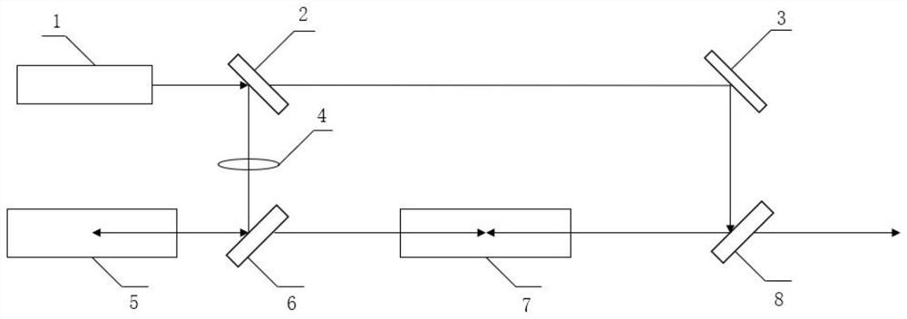
[0045] Embodiment 1: the pump source 1 selects a single longitudinal mode laser with a wavelength of 1064 nm and a pulse width of 1 ns, the focal length of the convex lens 4 is 10 cm, the length of the SRS generation pool 5 and the SRS amplification pool 7 are both 10 cm, and the two dielectric pools Select the Raman frequency shift as 1047.3cm -1 , Ba(NO 3 ) 2 The crystal finally outputs Stokes seed light (first-order output) with a wavelength of 1197nm. The optimal pulse output is obtained by adjusting the output energy of the laser and the fraction of the beam splitter 2. At this time, the measured energy conversion efficiency is 15%.

Embodiment 2

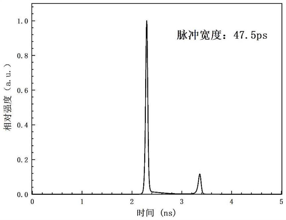
[0046] Embodiment 2: the wavelength used by the pump source 1 is 1064nm, the divergence angle is 0.45mrad, the peak power is 2.1MW, and the pulse width is 1ns; the medium selection Raman frequency shift in the SRS generation pool 5 and the SRS amplification pool 7 is 1047.3cm -1 , Ba(NO 3 ) 2 Crystal, the cell length of SRS generation cell 5 and SRS amplification cell 7 are both 10cm, the focal length of convex lens 4 is 16.2cm, the distance between convex lens 4 and the cell mirror of SRS generation cell 5 is 10cm, and other device models are not limited. The numerical simulation results of this example are as follows image 3 As shown, the laser pulse output with a wavelength of 1198nm and a pulse width of 47.5ps ​​was finally obtained.

Embodiment 3

[0047] Embodiment 3: The difference between the parameters in this embodiment and Embodiment 2 is that by changing the Raman gain coefficient of different media and the numerical simulation of the phonon lifetime of the medium; Figure 4 It is the numerical simulation diagram of the phonon lifetime of 80ps and the gain coefficients of 3cm / GW, 7cm / GW, 11cm / GW, 15cm / GW and 19cm / GW at 1064nm, and the corresponding pulse widths of the laser pulse output are 78ps and 56ps respectively , 47.5ps, 45.5ps and 43ps; Figure 5 It is the numerical simulation diagram under the gain coefficient of 11cm / GW at 1064nm, and the phonon lifetimes are 0.02ns, 0.05ns, 0.08ns, 0.11ns and 0.14ns respectively, and the corresponding pulse widths of the laser pulse output are 40ps, 44.5ps, 47.5 ps, 53ps and 56.5ps.

[0048] It can be seen from the figure that the larger the gain coefficient, the shorter the Raman active medium with the phonon lifetime is, the more helpful it is to obtain the pulse outp...


PUM

PropertyMeasurementUnit
wavelengthaaaaaaaaaa
Gain coefficientaaaaaaaaaa

Abstract

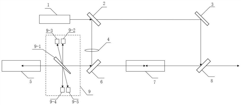
The invention relates to an ultrashort pulse laser generating an amplification structure based on stimulated Raman scattering. The ultrashort pulse laser comprises a pumping source; a beam splitter; a reflector; a convex lens; an SRS generation pool; a first dichroscope; an SRS amplification pool; a second dichroscope; the pumping source emits single longitudinal mode pumping light which is divided into two beams by the beam splitter; the first light beam is focused and reflected by a convex lens and a first dichroscope to enter an SRS generation pool for backward stimulated Raman scattering, and reverse Stokes seed light is generated and enters an SRS amplification pool through the first dichroscope; the second light beam is reflected by the reflector and the second dichroscope and then enters the SRS amplification pool to oppositely meet the reverse Stokes seed light, and the reverse Stokes seed light extracts the energy of the second light beam for amplification; and the compressed and amplified ultrashort pulse Stokes seed light is output through the second dichroscope. Pump light is compressed and amplified through the structure, high energy output can be obtained, and compared with a mode-locked laser, picosecond laser of tens of millijoules can be directly generated.

Description

technical field [0001] The invention relates to the technical field of short pulse lasers, in particular to an ultrashort pulse laser generating an amplification structure based on stimulated Raman scattering. Background technique [0002] Ultrashort pulse lasers are widely used in real life. Ultrashort pulse lasers are required in the fields of laser radar, micro-nano processing, and laser medical treatment, and some fields require ultrashort pulse lasers with high energy. There are currently three schemes for obtaining short pulses, (1) Q-switching technology; (2) mode-locking technology; (3) stimulated scattering technology. [0003] (1) Q-switching technology obtains pulses with high peak power and narrow width by adjusting the Q value, but the Q-switching technology is limited by the cavity length and can only generate sub-nanosecond laser pulses [such as invention patent publication number: CN109004507A, Patent name: controllable passive Q-switched infrared laser]; (2...

Claims


Application Information

Patent Timeline
Patent Type & Authority Applications(China)
IPC IPC(8): H01S3/30H01S3/11
CPCH01S3/30H01S3/11
Inventor 刘照虹李绍文罗甜甜樊榕纪文强扈雪雷王雨雷吕志伟
Owner HEBEI UNIV OF TECH
Learn More