Analog audio signal active low-pass filter circuit of operational amplifier in multimedia communication equipment
A low-pass filter circuit, multimedia communication technology, applied in the network using active components, electrical components, multi-terminal network and other directions, can solve the problem that the op amp is easily affected by EMI, achieve good EMI immunity performance, strengthen the system Design, reduce the effect of near-field EMI
- Summary
- Abstract
- Description
- Claims
- Application Information
AI Technical Summary
Problems solved by technology
Method used
Image

Examples
Embodiment 1
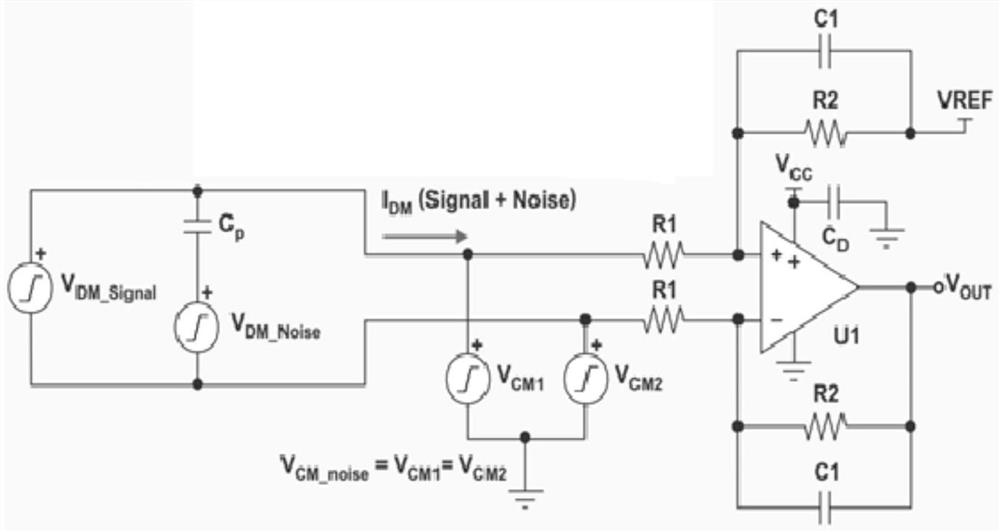
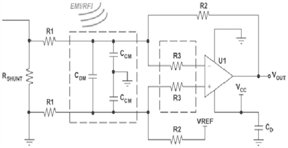
[0044] An active low-pass filter circuit for an analog audio signal of an operational amplifier in a multimedia communication device, comprising: active filtering of differential mode noise, reduction of input common mode noise, improvement of immunity to RFI and other high-frequency EMI, Low output impedance reduces interference, simulation comparison verification, the active filtering of the differential mode noise is coupled to the DM noise in the input signal through the parasitic capacitance (CP), the combined signal and noise are controlled by a first-order active low-pass filter Receive, the low-pass cut-off frequency of the differential op amp circuit is set just above the desired signal bandwidth determined by R2 and C1, the higher frequencies are attenuated by 20dB / decade, if more attenuation is required, use a higher order active filter; the stated reduction in input common-mode noise is the noise voltage that is common at the two op-amp inputs and is not part of the...
Embodiment 2
[0046] The analog audio signal active low-pass filter circuit of the operational amplifier in the multimedia communication device described in Embodiment 1, with figure 1 Shows DM noise coupled into the input signal through parasitic capacitance (CP). The combined signal and noise are received by a first-order active low-pass filter. The low-pass cutoff frequency of the differential op amp circuit is set just above the desired signal bandwidth determined by R2 and C1. Higher frequencies are attenuated by 20dB / decade. If more attenuation is required, a higher order active filter (for example, -40 or -60dB / decade) can be used. Resistors with <1% tolerance are recommended. Also, capacitors with very good temperature coefficients (NPO, COG) and a 5% (or <5%) tolerance give the best filter performance.
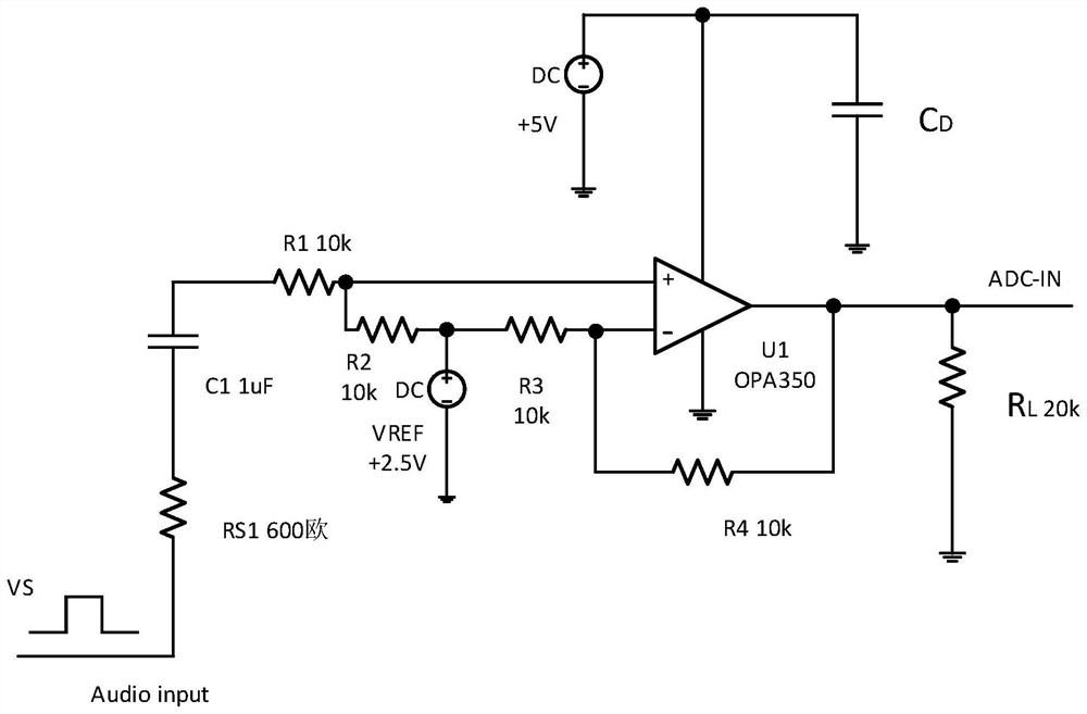
[0047] The op amp provides gain and improves load carrying capability. The load is not directly connected to the RC network, but is connected through an operational amplifier ...
Embodiment 3
[0049] The analog audio signal active low-pass filter circuit of the op-amp in the multimedia communication device described in Embodiment 1, the described input common mode noise reduction, the attached figure 1 , common-mode (CM) noise sources also contribute noise at the circuit input. CM noise can be described as the noise voltage that is common (or identical) at the two op amp inputs and is not part of the expected differential-mode signal that the op amp is trying to measure or condition. CM noise can occur in a variety of ways. An example is a system where the ground reference of one circuit is at a different voltage potential than the second circuit it interfaces with. The difference in "ground" voltage can be on the order of millivolts or several volts, and can also occur at many different frequencies. These differences in voltage can cause unintended voltage drops and can interfere with the flow of current in connected circuits.
[0050] Complex communication devi...
PUM
 Abstract
Description
Claims
Application Information
 - R&D
- Intellectual Property
- Life Sciences
- Materials
- Tech Scout
- Unparalleled Data Quality
- Higher Quality Content
- 60% Fewer Hallucinations
Browse by: Latest US Patents, China's latest patents, Technical Efficacy Thesaurus, Application Domain, Technology Topic, Popular Technical Reports.
© 2025 PatSnap. All rights reserved.Legal|Privacy policy|Modern Slavery Act Transparency Statement|Sitemap|About US| Contact US: help@patsnap.com