Preparation method of phase change heat reservoir of electronic equipment

A technology for electronic equipment and heat storage, which is applied in the field of preparation of phase change heat storage for electronic equipment, and can solve the difficulty of preparing and installing the internal heat conduction core 2, increasing the thermal resistance of the heat conduction core 2, and leakage of liquid phase change materials 3 and other problems, to achieve the effect of shortening the process flow and manufacturing cycle, short manufacturing cycle, and high utilization rate of structural space

Pending Publication Date: 2022-04-29
10TH RES INST OF CETC
View PDF10 Cites 0 Cited by
  • Summary
  • Abstract
  • Description
  • Claims
  • Application Information

AI Technical Summary

Problems solved by technology

[0004] ①The box body and the cover plate are combined by vacuum brazing or electron beam welding, and the welding area is large, which is prone to welding defects that cause the leakage of the liquid phase change material 3;
[0005] ②The heat conduction core 2 with better heat conduction enhancement effect is generally a porous structure, which is assembled or welded separately with the box body, which in

Method used


Image

  • Preparation method of phase change heat reservoir of electronic equipment
  • Preparation method of phase change heat reservoir of electronic equipment
  • Preparation method of phase change heat reservoir of electronic equipment

Examples


Embodiment Construction

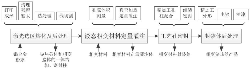
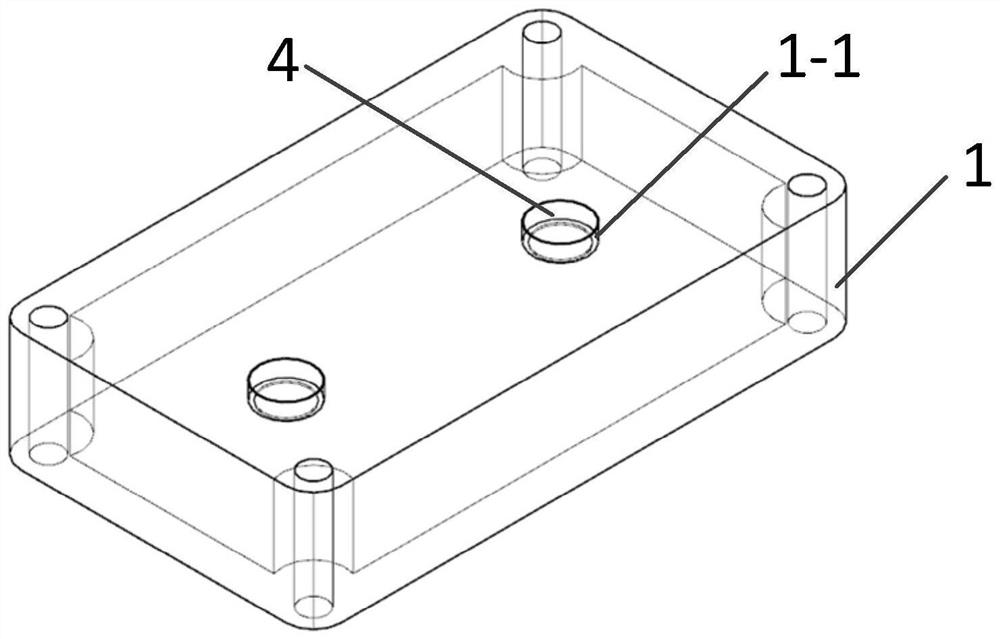
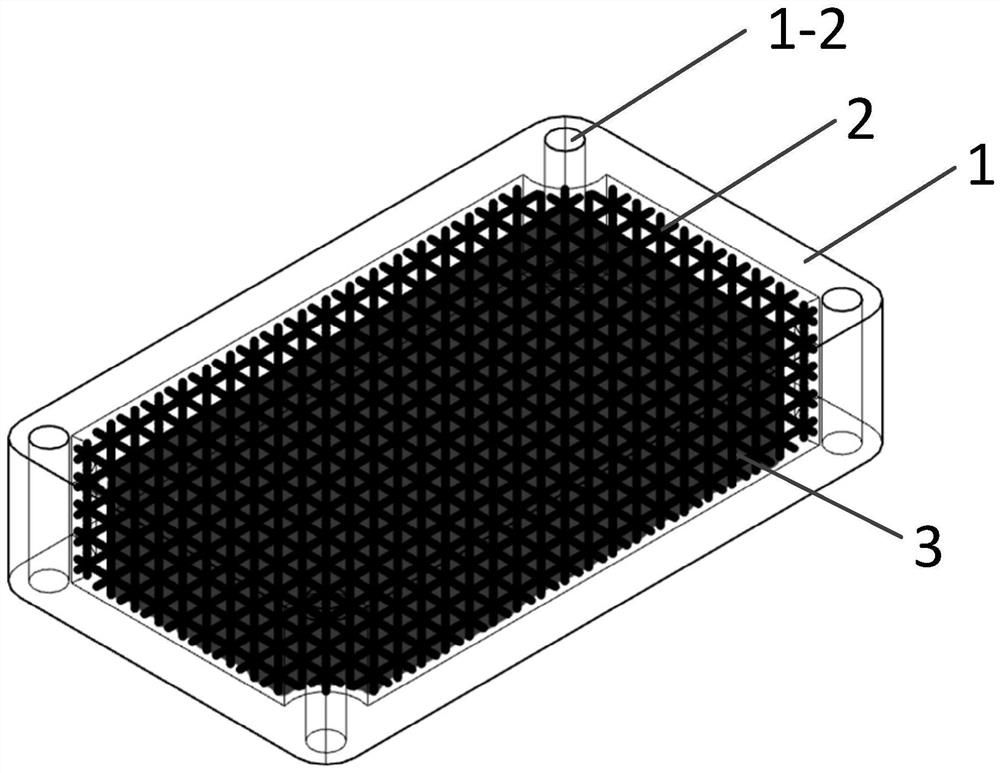
[0032] refer to figure 1 , figure 2 . The process hole 1-1 of the box body is welded and joined with the sealing column to form a cavity structure box body with uniform thickness on each surface; a porous lattice structure is designed, and the diameter of the lattice rod forms a gradient change in multiple directions The three-dimensional model of the thermally conductive core 2 conforming to the inner cavity of the phase change box 1 is assembled to the inner cavity of the phase change box 1 provided with two process holes 1-1 to form the thermally conductive core 2 and the phase change box 1 The integrated model of the integrated model; the aluminum alloy powder is used to print and form by laser selective melting equipment, and after cleaning the residual powder, heat treatment, wire cutting and other processes, the integrated structure and sealing of the phase change heat storage core 2 and the phase change box 1 are obtained. Column; the low-temperature solid-liquid ph...


PUM

PropertyMeasurementUnit
Rod diameteraaaaaaaaaa
Tensile strengthaaaaaaaaaa
Thermal conductivityaaaaaaaaaa

Abstract

According to the preparation method of the phase change heat reservoir of the electronic equipment, the sealing performance is good, the thermal resistance is small, the impact vibration resistance is high, and the heat exchange efficiency is high. According to the technical scheme, the method comprises the following steps: assembling a porous structure heat conduction core body which is designed to form gradient changes in dot matrix rod diameters in multiple directions and is conformal with an inner cavity of a phase change box body into the inner cavity of the phase change box body to form an integrated model of the heat conduction core body and the phase change box body; aluminum alloy powder is printed and formed through selective laser melting equipment, and an integrated structure of a heat conduction core body and a phase change box body of the phase change heat reservoir and a sealing column are obtained; the low-temperature solid-liquid phase-change material with the melting point of 40-90 DEG C and stable physical property is poured into the phase-change box body to form a phase-change material quantitative pouring body through the procedures of measuring the internal pore volume of the phase-change box body, performing vacuum heating quantitative pouring and the like; and welding or bonding combination is carried out after sealing through the process holes of the phase change box body, and the phase change material packaging body of the phase change heat reservoir product is assembled and sealed.

Description

technical field [0001] The invention relates to the field of energy storage and temperature control of electronic equipment heat dissipation technology, in particular to a preparation method of a phase change heat storage device for electronic equipment. Background technique [0002] As the power of electronic components in electronic equipment continues to increase, the physical size continues to decrease, and the heat flux continues to increase, resulting in excessive temperature of electronic devices during operation, which will inevitably affect the performance of electronic components. Effective temperature control. PCM is a phase change material used for temperature control of common electronic equipment. According to the principle of phase change temperature control, heat storage requires a certain carrier. There are two forms of material heat storage, one is sensible heat storage, that is, heat is stored by the heat capacity of the material, In the process of heat s...

Claims


Application Information

Patent Timeline
IPC IPC(8): H05K7/20
CPCH05K7/2029Y02E60/14
Inventor 雷涛赖复尧阎德劲苏欣陶亚平
Owner 10TH RES INST OF CETC
Why Eureka
Try Eureka