Gel electrolyte and gel electrolytic cell
A technology of gel electrolyte and electrolyte, which is applied in non-aqueous electrolyte batteries, non-aqueous electrolyte batteries, electrolyte immobilization/gelation, etc., can solve problems such as difficulties in low-temperature characteristics, and achieve the goal of improving overall battery performance and cycle characteristics Effect
- Summary
- Abstract
- Description
- Claims
- Application Information
AI Technical Summary
Problems solved by technology
Method used
Image
Examples
preparation example Construction
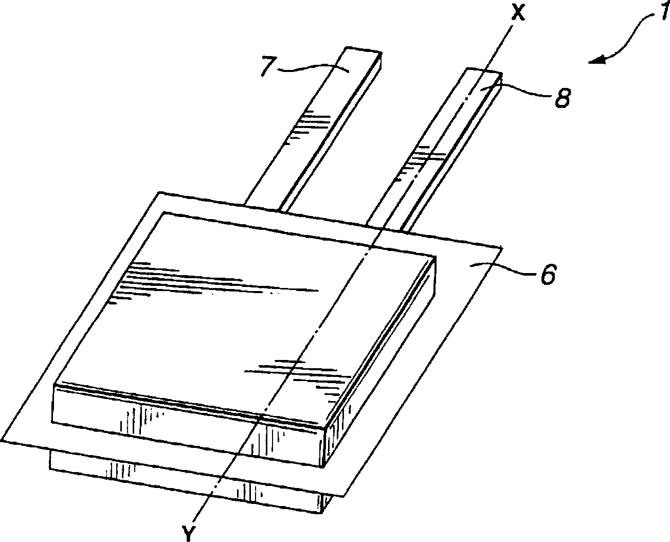
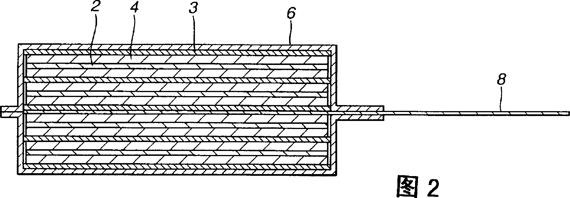
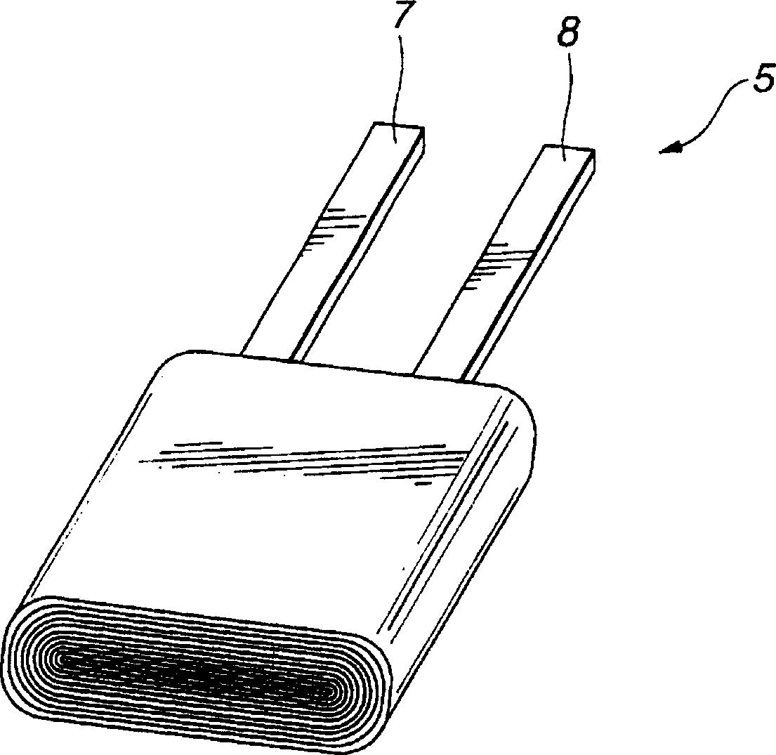
[0052] A method of manufacturing the gel electrolyte battery 1 will be described below.
[0053] For the positive electrode 2, a positive electrode mixture containing a positive electrode active material and a binder is uniformly coated on a metal foil serving as a positive electrode current collector 2b, for example, on an aluminum foil, and dried in situ to form an active material layer of the positive electrode 2 2a, to prepare the positive electrode sheet. As the binder of the positive electrode mixture, any available known binder can be used. In addition, any known usable additives and the like may also be added to the positive electrode mixture.
[0054] Then, gel electrolyte layer 4 is formed on active material layer 2 a of positive electrode 2 . In order to form the gel electrolyte layer 4, first, an electrolyte salt is dissolved in a nonaqueous solvent to prepare a nonaqueous electrolytic solution. The matrix polymer is added to the non-aqueous electrolytic solutio...
Embodiment 1
[0068] First, positive and negative electrodes are prepared.
[0069] To prepare the positive electrode, 92% by weight of lithium cobaltate (LiCoO 2 ), 3% (weight) of polyvinylidene fluoride powder and 5% (weight) of graphite powder are dispersed in N-methylpyrrolidone (NMP) to make a slurry, and this slurry is coated on the positive electrode collector both sides of the aluminum foil. The obtained product was dried at 100° C. for 24 hours under reduced pressure. The dried product is pressed with a roller press under appropriate pressure to obtain a positive electrode sheet.
[0070] This positive electrode sheet was cut into a rectangle of 50 mm×300 mm, and an aluminum foil wire with a thickness of 50 μm was welded to the part of the positive electrode current collector not coated with the positive electrode mixture as a positive electrode terminal. Thus, a positive electrode was produced.
[0071] In order to prepare the negative electrode, 91% (weight) of artificial gra...
Embodiment 1 to 32
[0078] A gel electrolyte battery was prepared in the same manner as in Example 1 except that the gel electrolyte composition listed in Table 1 was used.
[0079] Among them, in Example 21, LiN(CF 3 SO 2 ) 2 As an electrolyte salt to replace LiPF 6 .
[0080] In Example 22, lithium nickel cobaltate LiCo 0.8 Ni 0.2 o 2 It is used as a positive electrode active material to replace lithium cobalt oxide, and carbon that is difficult to graphitize is used instead of artificial graphite as a negative electrode active material.
[0081] Also, in Examples 23 to 28, difluoroanisole was added in an amount of 1% by weight to the solvent for the electrolytic solution.
[0082] EC(weight%)
PUM
 Abstract
Description
Claims
Application Information
 - R&D
- Intellectual Property
- Life Sciences
- Materials
- Tech Scout
- Unparalleled Data Quality
- Higher Quality Content
- 60% Fewer Hallucinations
Browse by: Latest US Patents, China's latest patents, Technical Efficacy Thesaurus, Application Domain, Technology Topic, Popular Technical Reports.
© 2025 PatSnap. All rights reserved.Legal|Privacy policy|Modern Slavery Act Transparency Statement|Sitemap|About US| Contact US: help@patsnap.com


