Large-temperature-difference high-temperature heat pump hot water unit driven by engine

An engine-driven, high-temperature heat pump technology, used in refrigerators, compressors, refrigeration components, etc., to achieve the effects of high outlet water temperature, high work efficiency, and reasonable unit structure

Pending Publication Date: 2022-05-06
SHANGHAI AIRUTE AIR CONDITIONING SYST
View PDF0 Cites 0 Cited by
  • Summary
  • Abstract
  • Description
  • Claims
  • Application Information

AI Technical Summary

Problems solved by technology

Engine-driven heat pumps have significant economic and environmental benefits, but the current engine-driven heat pumps are still small multi-connected air conditioners or products with a heating outlet temperature of about 50°C

Method used


Image

  • Large-temperature-difference high-temperature heat pump hot water unit driven by engine
  • Large-temperature-difference high-temperature heat pump hot water unit driven by engine
  • Large-temperature-difference high-temperature heat pump hot water unit driven by engine

Examples


Embodiment 2

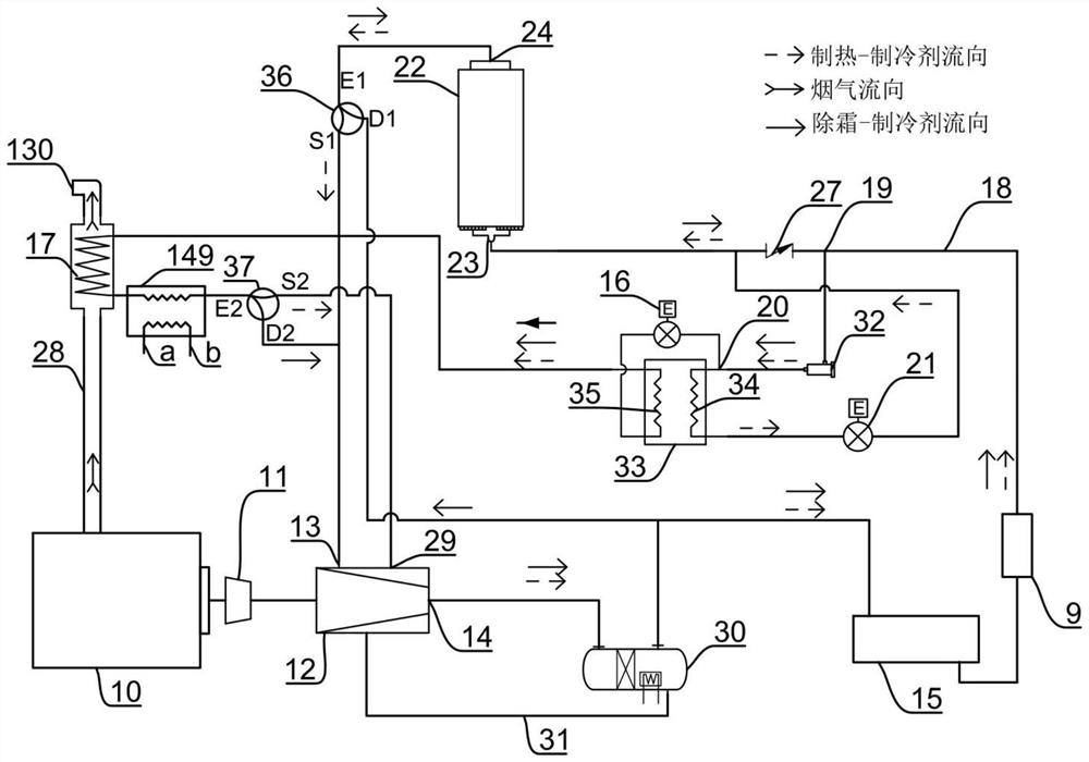
[0067] The work process of embodiment two is basically the same as embodiment one, and the difference is:

[0068] Such as image 3 As shown, no matter in the heating mode or the defrosting mode, the refrigerant gas discharged from the exhaust port 14 of the compressor 12 needs to enter the oil separator 30 through the oil refrigerant inlet, and the oil separator 30 will lubricate the refrigerant gas After the oil is separated, the separated lubricating oil returns to the compressor 12 through the lubricating oil circuit 31 .

[0069] Regardless of the heating mode or the defrosting mode, the refrigerant liquid must pass through the drying filter 32 to dry. The heating mode enters the flue gas refrigerant heat exchanger 17 and the cooling water refrigerant heat exchanger 149 through the first throttle valve 16, and enters the second heat exchanger 22 through the second throttle valve 21; The first throttle valve 16 enters the flue gas refrigerant heat exchanger 17 and the co...

Embodiment 3

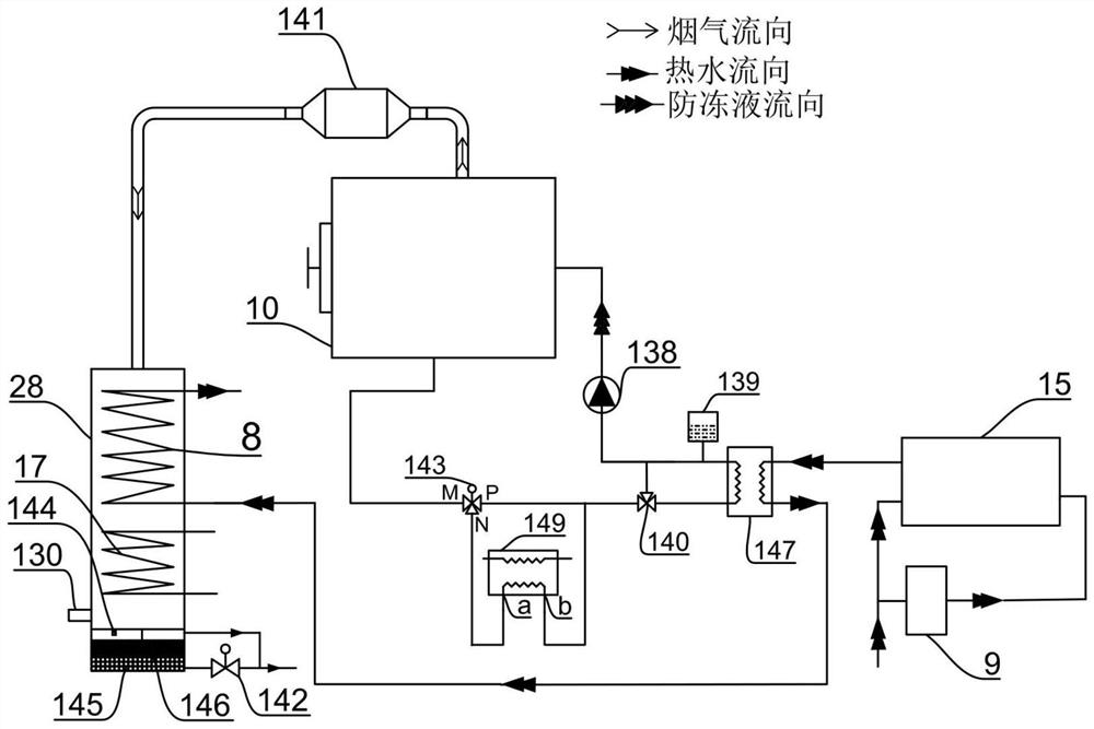
[0071] Figure 4 It is a schematic diagram of the connection and flow diagram of the peripheral parts of the engine-driven large-temperature-difference high-temperature heat pump hot water unit in Embodiment 3 of the present invention.

[0072] Such as Figure 4 As shown, Embodiment 3 provides an engine-driven engine-driven large temperature difference high-temperature heat pump water heater unit. The engine-driven large temperature difference high-temperature heat pump water heater unit differs from Embodiment 1 only in that: The cooling water heat exchanger 8 is arranged between the cylinder liner of the engine 10 and the cooling water inlet of the radiator 147. In this embodiment, the flue gas cooling water heat exchanger 8 is arranged between the cylinder liner of the engine 10 and the cooling water three-way valve 143 . Therefore, the cooling water from the cylinder liner of the engine 10 will first flow through the flue gas cooling water heat exchanger 8 and then enter...


PUM


Abstract

The invention provides an engine-driven large-temperature-difference high-temperature heat pump hot water unit which comprises a compressor, a first heat exchanger, a second heat exchanger, an economizer and an engine, the compressor is provided with an exhaust port, an air suction port and an air supply port, and the engine is provided with an engine cylinder sleeve. Refrigerant from the exhaust port releases heat and is condensed into liquid in the first heat exchanger, the liquid is divided into two paths after being subjected to heat release through the subcooler, one path of refrigerant flows through the economizer to release heat and be cooled, and the refrigerant returns to the compressor from the air suction port after being subjected to heat absorption and evaporation in the second heat exchanger, and the other path of refrigerant flows through the air suction port after being subjected to heat absorption and evaporation in the subcooler. After part of or all of the hot water flows through the cooler and absorbs the heat of the refrigerant liquid, all of the hot water flows into the first heat exchanger to absorb the condensation heat of the refrigerant; and then heat is directly or indirectly absorbed from the engine cylinder sleeve and the flue gas cooling water heat exchanger in sequence.

Description

technical field [0001] The invention belongs to the technical field of heat pumps, in particular to an engine-driven large temperature difference high-temperature heat pump hot water unit. Background technique [0002] The temperature difference of the primary water for regional heating in winter in the north is generally between 25°C and 40°C, and the outlet water temperature is between 75°C and 90°C. Boilers are widely used as heating sources. The thermal efficiency of boilers is low and the fuel consumption is large. The highest temperature of hot water produced by conventional electric heat pumps is about 73°C. Electric heat pumps cannot directly replace winter heating boilers because the outlet water temperature is not high enough. Engine-driven heat pumps have the characteristics of high efficiency, low operating costs, and low emission levels. With the implementation of sustainable development strategies and the continuous strengthening of energy conservation and envi...

Claims


Application Information

Patent Timeline
IPC IPC(8): F24H4/02F25B13/00F25B41/26F25B41/34F25B41/42F25B43/00F25B43/02F25B47/02
CPCF24H4/02F25B13/00F25B41/26F25B47/025F25B43/003F25B43/02F25B41/42F25B41/34
Inventor 张小力
Owner SHANGHAI AIRUTE AIR CONDITIONING SYST
Why Eureka
Try Eureka