Eureka AIR delivers breakthrough ideas for toughest innovation challenges, trusted by R&D personnel around the world.

Gravity and compressed air combined energy storage system and working method thereof

A compressed air and energy storage system technology, applied in the field of energy storage systems, can solve the problems of low coincidence between power peak and load peak time, large impact on surrounding ecological environment, short response time of energy storage efficiency, etc., and achieve fast adjustment speed , High energy utilization rate and long service life

Active Publication Date: 2022-05-10
NORTH CHINA ELECTRIC POWER UNIV (BAODING)
View PDF5 Cites 5 Cited by
  • Summary
  • Abstract
  • Description
  • Claims
  • Application Information

AI Technical Summary

Problems solved by technology

Its advantage is flexible power conversion and short start-up time; its disadvantage is that it is not easy to choose the location of its power station, and it has a great impact on the surrounding ecological environment and requires a large investment
The operating principle of gravity energy storage is similar to that of pumped water storage, except that flowing water is turned into solid weights to achieve energy storage. Its advantages are: large-scale energy storage, high energy storage efficiency (80%-90%), Short response time, long running time (30-50 years), low construction cost, and flexible layout; but its disadvantages are: low energy density (0.2-0.4Wh / kg), low power per unit module
[0006] Now, with the development of the national "West-to-East Electricity Transmission" strategy, how to overcome the limitations of the existing long-term energy storage technology on geographical, spatial and climatic conditions, At the same time, it can solve the problem of energy consumption in the western region, avoid the problem of low overlap between the power peak and load peak of new energy power generation in time, and finally realize the reliable grid connection of new energy power generation has become an urgent problem to be solved

Method used


Image

  • Gravity and compressed air combined energy storage system and working method thereof

Examples


Embodiment Construction

[0032]In order to make the objectives, technical solutions and advantages of the present invention clearer, the technical solution of the present invention will be further described in detail below in conjunction with the accompanying drawings in specific embodiments of the present invention. In the drawings, like reference numerals designate like or similar functional device elements throughout. The described embodiment is a part of the embodiment of the present invention, and the described content and directional words can not be limited to the embodiment, but a detailed explanation of the present invention rather than limitation:

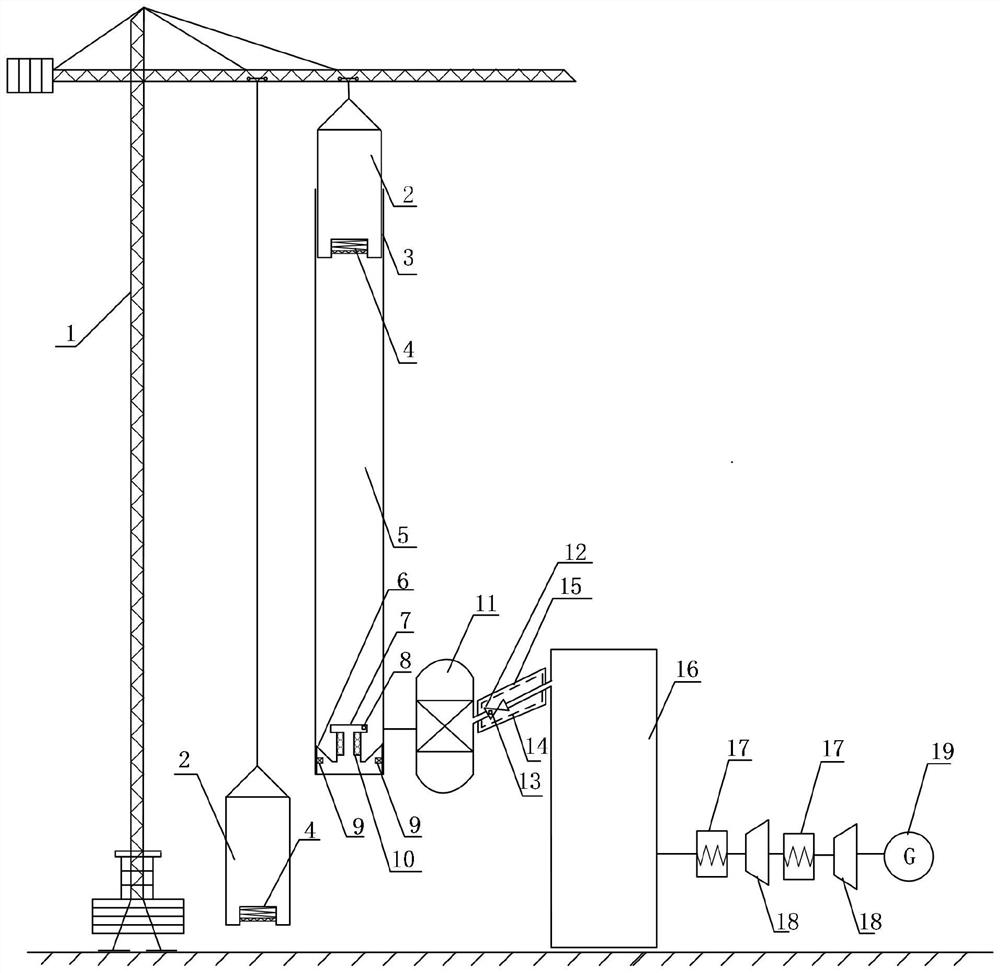
[0033] In a broad embodiment of the present invention, an energy storage system combining gravity and compressed air is characterized in that the energy storage system includes a tower crane 1, a weight 2, a cylinder 5, a sealing end cover 6, a cold storage Heat exchanger 11 , air storage chamber 16 , air expansion unit 17 and generator 18 . The...


PUM


Abstract

The invention provides a gravity and compressed air combined energy storage system and a working method thereof, and belongs to the technical field of energy storage. The system comprises a tower crane, a heavy block, an air compression unit, a cold accumulation heat exchanger, an air storage chamber, an air expansion unit and a generator. The tower crane lifts the heavy block to consume electric energy, and the heavy block freely falls to compress air in the air compression unit; high-pressure hot air passing through the air compression unit is changed into high-pressure cold air after passing through the cold storage heat exchanger, the high-pressure cold air enters the air storage chamber through the energy storage pipeline, and a heating body on the energy storage pipeline determines whether to heat according to the temperature tested by a temperature sensor so as to ensure that the energy storage pipeline and an air inlet valve cannot be frozen; an outlet of the air storage chamber is connected with an inlet of the air expansion unit through an energy release pipeline, an outlet of the air expansion unit is connected with the generator, and the generator generates electricity under high-temperature and high-pressure air impact. Wherein a sealing device is arranged between the heavy block and the air compression unit, and a blind hole internally provided with a buffer device is formed below the heavy block. Compressed air energy storage and gravitational potential energy storage are combined, the advantages that compressed air energy storage is high in energy density and gravitational energy storage is flexible in arrangement and high in efficiency are achieved, advantage complementation is achieved, it can be guaranteed that a power grid is safer, more stable, more reliable and more environmentally friendly, and the peak load shifting effect is achieved.

Description

technical field [0001] The invention belongs to the technical field of energy storage, and in particular relates to an energy storage system combining gravity and compressed air and a working method thereof. Background technique [0002] In recent years, with the vigorous development of renewable energy in my country, the adverse effects brought about by the characteristics of intermittent and fluctuating power generation have gradually become prominent, and some areas with unbalanced power source composition and load levels have higher curtailment of wind and light. rate, resulting in a large amount of waste of electric energy, but also poses a major challenge to the stable operation of the power grid. In order to ensure the stability, safety and economy between power supply and demand, the vigorous development of energy storage technology is urgently needed. The important support of the new power system with new energy as the main body is of great significance to promote t...

Claims


Application Information

Patent Timeline
Patent Type & Authority Applications(China)
IPC IPC(8): F04B35/01F04B41/02F04B39/06F01K27/00F01K25/08
CPCF04B35/01F04B41/02F04B39/06F01K27/00F01K25/08Y02E60/16Y02E70/30
Inventor 王乐程王银顺王建宏李继春夏芳敏
Owner NORTH CHINA ELECTRIC POWER UNIV (BAODING)
Why Eureka
Eureka Blog
Learn More