
Memory, submarine cable fault detection and diagnosis method, device, equipment and system

A technology for submarine cable and fault detection, which is applied to measurement devices, testing of machinery/structural components, instruments, etc. It can solve problems such as distortion of the original waveform of signals, failure of real-time monitoring and effective transmission of fault signals, and failure of submarine cables to be discovered in time. , to achieve the effect of improving the accuracy

Pending Publication Date: 2022-05-10
CHINA PETROLEUM & CHEM CORP +1
View PDF0 Cites 0 Cited by
  • Summary
  • Abstract
  • Description
  • Claims
  • Application Information

AI Technical Summary

Problems solved by technology

[0003] With the increasingly complicated laying of submarine cables, the problem of difficult fault diagnosis has gradually emerged, especially for some non-fiber composite submarine cables, whose fault signals cannot be monitored in real time and effectively transmitted through optical fiber sensing technology
[0004] The inventor found through research that in the prior art, for non-fiber composite submarine cables, the fault diagnosis method is mostly the traditional partial discharge detection method. This method is affected by the strong electromagnetic interference of the sea tide, and the original waveform of the signal is seriously distorted. The practical application of non-electrical faults caused by external force damage, rock wear, insulation erosion, etc. is not good, so that the submarine cable cannot be detected in time when a slight mechanical damage fault occurs

Method used


Image

  • Memory, submarine cable fault detection and diagnosis method, device, equipment and system
  • Memory, submarine cable fault detection and diagnosis method, device, equipment and system
  • Memory, submarine cable fault detection and diagnosis method, device, equipment and system

Examples


Embodiment 1

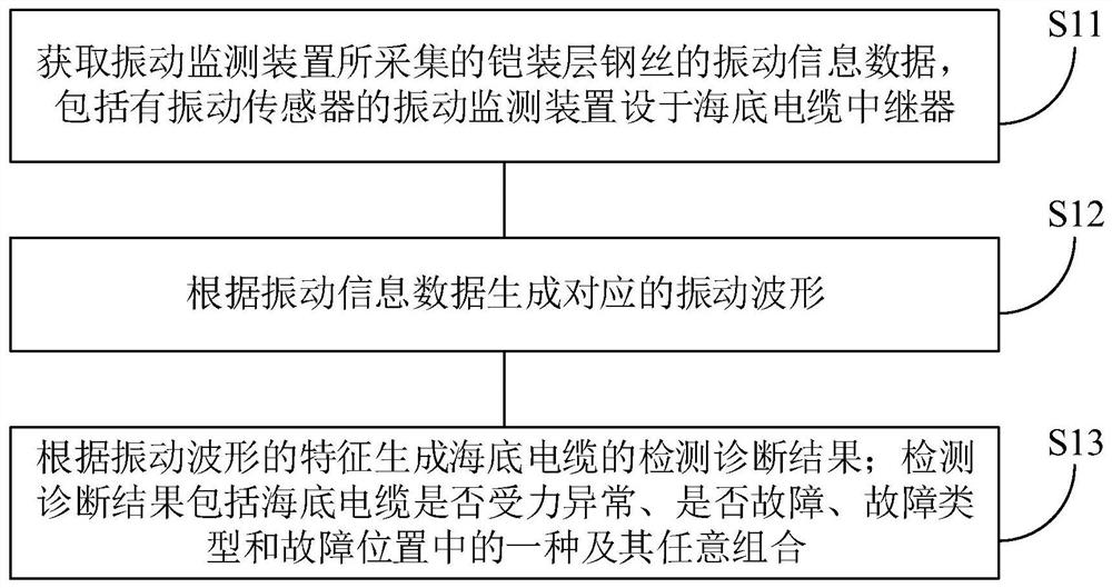
[0050] In order to improve the accuracy of fault detection and diagnosis of submarine cables in the event of mechanical damage, such as figure 1 As shown, a method for detecting and diagnosing a submarine cable fault is provided in an embodiment of the present invention, comprising steps:

[0051] S11. Obtain the vibration information data of the armored steel wire collected by the vibration monitoring device; the vibration monitoring device including the vibration sensor is arranged in the submarine cable repeater;

[0052]The core inventive idea of ​​the embodiment of the present invention includes: the inventor found through research that when the submarine cable is mechanically damaged, it will first impact the armored steel wire as the protective layer of the submarine cable. Good metal material, therefore, when the submarine cable is mechanically damaged, it will inevitably cause corresponding changes in the vibration waves in the steel wire of the armor layer.

[0053]...

Embodiment 2

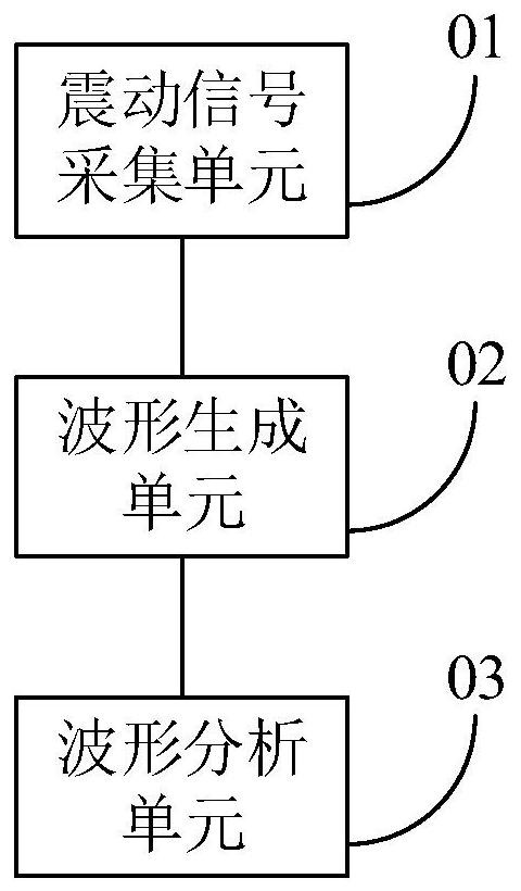
[0083] On the other side of the embodiment of the present invention, a submarine cable fault detection and diagnosis device is also provided, figure 2 A schematic structural diagram of a submarine cable fault detection and diagnosis device provided by an embodiment of the present invention is shown, and the submarine cable fault detection and diagnosis device is a figure 1 The device corresponding to the method for detecting and diagnosing submarine cable faults in the corresponding embodiment, that is, implemented in the form of a virtual device figure 1 In the submarine cable fault detection and diagnosis method in the corresponding embodiment, each virtual module constituting the submarine cable fault detection and diagnosis device may be executed by electronic equipment, such as network equipment, terminal equipment, or server. Specifically, the submarine cable fault detection and diagnosis device in the embodiment of the present invention includes:

[0084] The vibratio...

Embodiment 3

[0089] In an embodiment of the present invention, a memory is also provided, wherein the memory includes a software program, and the software program is suitable for a processor to execute figure 1 Each step in the corresponding submarine cable fault detection and diagnosis method.

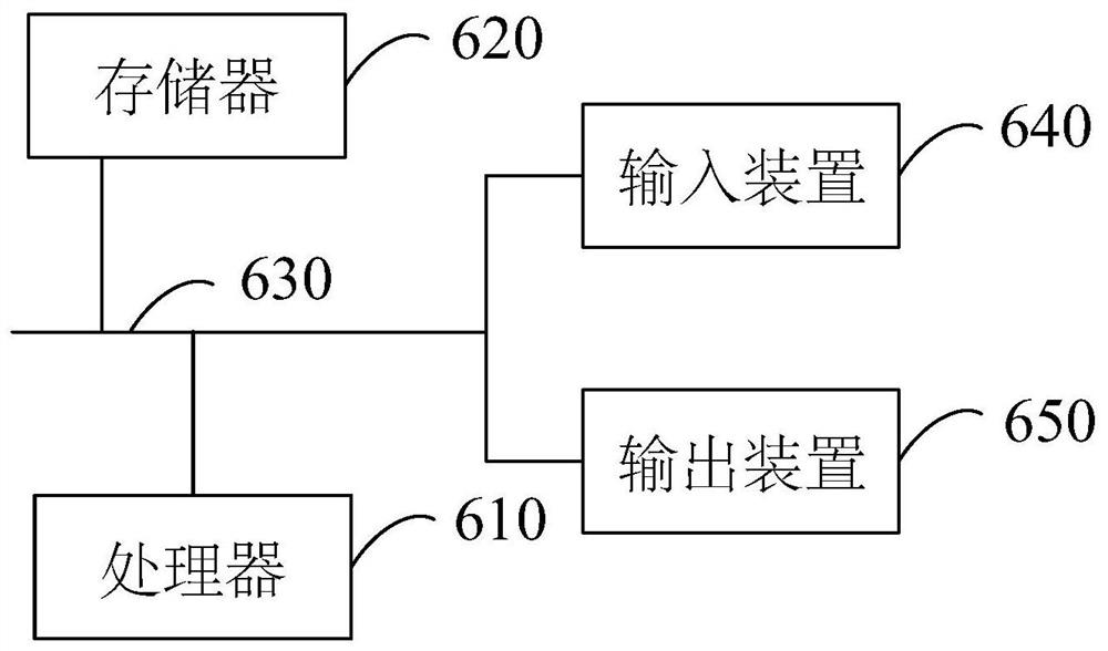
[0090] The embodiment of the present invention can be realized by means of software programs, that is, by writing figure 1 Corresponding software program (and instruction set) of each step in the submarine cable fault detection and diagnosis method, the software program is stored in the storage device, and the storage device is set in the computer device, so that the processor of the computer device can call the software program software programs to achieve the purposes of the embodiments of the present invention.


PUM


Abstract

The invention discloses a memory, a submarine cable fault detection and diagnosis method, a submarine cable fault detection and diagnosis device and submarine cable fault detection and diagnosis equipment, and the method comprises the steps: obtaining the vibration information data, collected by a vibration monitoring device, of an armor layer steel wire; comprising a vibration sensor is arranged on a submarine cable repeater; generating a corresponding vibration waveform according to the vibration information data; generating a detection and diagnosis result of the submarine cable according to the characteristics of the vibration waveform; the detection and diagnosis result comprises one or any combination of whether the submarine cable is abnormal in stress, whether the submarine cable is faulty, a fault type and a fault position; the submarine cable fault detection and diagnosis method is not affected by sea tide strong electromagnetic interference, so that judgment can be made in time even if the submarine cable is slightly mechanically damaged, and the accuracy of fault detection and diagnosis is improved.

Description

technical field [0001] The invention relates to the field of oil refining and processing, in particular to storage and submarine cable fault detection and diagnosis methods, devices, equipment and systems. Background technique [0002] Submarine cables are the key link to ensure power transmission and distribution and information communication of offshore wind farms, offshore platforms and islands. The structure of the submarine cable itself is complex, and it has the characteristics of high working voltage, large current, and harsh operating environment; during the laying and operation of the submarine cable, it may be affected by various factors such as coiling, stretching, hooking, and tidal shock. Faults; the types of faults mainly include insulation aging and deterioration, insulation layer wear, short circuit, external force damage, protective corrosion, etc. [0003] As the laying of submarine cables becomes more and more complicated, the problem of difficult fault d...

Claims


Application Information

Patent Timeline
Patent Type & Authority Applications(China)
IPC IPC(8): G01M7/02G01H17/00
CPCG01M7/025G01H17/00
Inventor 时振堂王鹏凯刘维功孙进陶丽楠吴冠霖
Owner CHINA PETROLEUM & CHEM CORP
Learn More