Optical temperature sensing material and application thereof

A sensing material, optical technology, applied in the field of optical temperature sensing

Active Publication Date: 2022-05-13
WUYI UNIV
View PDF7 Cites 2 Cited by
  • Summary
  • Abstract
  • Description
  • Claims
  • Application Information

AI Technical Summary

Problems solved by technology

[0003] Compared with the thermally coupled fluorescence thermometer, the ratiometric temperature probe based on the non-thermally coupled energy level of rare earth ions is not limited by the thermally coupled energy level, which can improve the temperature measurement sensitivity and signal discrimination to a certain extent, but its sensitivity is still relatively large. room for improvement

Method used


Image

  • Optical temperature sensing material and application thereof
  • Optical temperature sensing material and application thereof
  • Optical temperature sensing material and application thereof

Examples


Embodiment 1

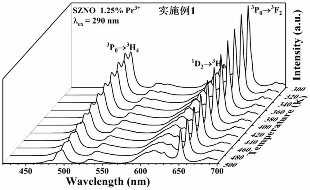
[0028] A kind of optical temperature sensing material SrZn of the present invention 0.33 Nb 0.67 o 3 :Pr 3+ (SZNO 1.25%Pr 3+ ), its preparation method comprises the following steps:

[0029] Raw material: SrCO 3 3mmol, Nb 2 o 5 1mmol, ZnO 1mmol, Pr 6 o 11 0.00625mmol, absolute ethanol 5mL.

[0030] 3mmol SrCO 3 , 1 mmol Nb 2 o 5 , 1mmol ZnO, 0.00625mmol Pr 6 o 11 , 5mL of absolute ethanol was mixed and ground in an agate mortar for 30min, the obtained powder was put into a corundum crucible and placed in a muffle furnace for calcination at 800°C for 2 hours, then poured into an agate mortar and ground again evenly, Then put it into a corundum crucible and calcinate in a muffle furnace at 1350°C for 8 hours. After taking out the sample, grind it until the particles are uniform.

Embodiment 2

[0032] A kind of optical temperature sensing material SrZn of the present invention 0.33 Nb 0.67 o 3 :Pr 3+ application, the specific method is:

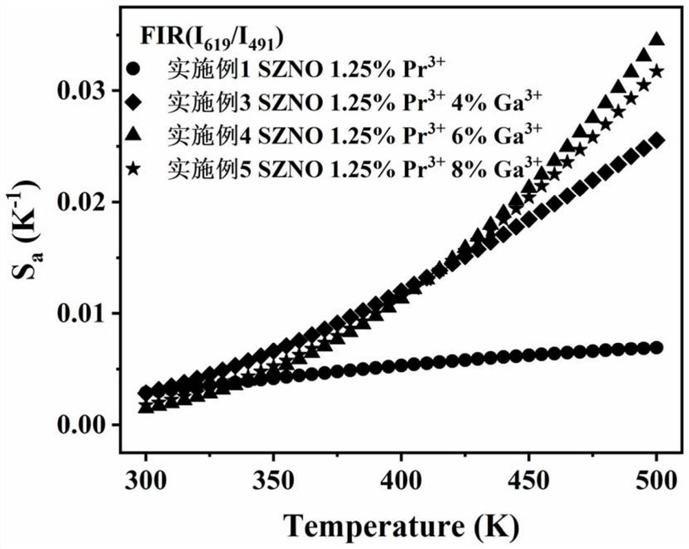
[0033] Excite SrZn with UV light at 290nm 0.33 Nb 0.67 o 3 :Pr 3+ , using FLS980 fluorescence spectrometer for SrZn 0.33 Nb 0.67 o 3 :Pr 3+ The fluorescent powder is tested for variable temperature emission spectrum, and the ratio of the emission peak intensity at 491nm (take the integrated intensity of 483nm to 508nm) to the emission peak intensity at 619nm (take the integrated intensity of 590nm to 640nm) is calculated. 619 / I 491 , and then compared in the function diagram, the required temperature can be obtained.

Embodiment 3

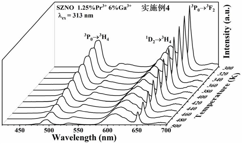
[0035] A kind of optical temperature sensing material SrZn of the present invention 0.33 Nb 0.67 o 3 :Pr 3+ / Ga 3+ (SZNO1.25%Pr 3+ 4%Ga 3+ ), its preparation method comprises the following steps:

[0036] Raw material: SrCO 3 3mmol, Nb 2 o 5 1mmol, ZnO 1mmol, Pr 6 o 11 0.00625mmol, Ga 2 o 3 0.06mmol, absolute ethanol 5mL.

[0037] 3mmol SrCO 3 , 1 mmol Nb 2 o 5 , 1 mmol ZnO, 0.00625 mmol Pr 6 o 11 , 0.06 mmol Ga 2 o 3 , 5mL of absolute ethanol was mixed and ground in an agate mortar for 30min, the obtained powder was put into a corundum crucible and placed in a muffle furnace for calcination at 800°C for 2 hours, then poured into an agate mortar and ground again evenly, Then put it into a corundum crucible and calcinate in a muffle furnace at 1350°C for 8 hours. After taking out the sample, grind it until the particles are uniform.


PUM


Abstract

The invention provides an optical temperature sensing material and application thereof, the material is an optical temperature sensing material SrZn0. 33Nb0. 67O3: Pr < 3 + > based on a non-thermal coupling energy level of Pr < 3 + >, the material is prepared by a high temperature solid phase method, and the material generates emission peaks with wavelengths at 491 nm, 619 nm and 651 nm under the excitation of ultraviolet light, and the emission peaks are respectively derived from transition emission of Pr < 3 + >: 3P0-3H4, 1D2-3H4 and 3P0-3F2. The fluorescence intensity ratio of the emission peak at the 619 nm to the emission peak at the 491 nm and the fluorescence intensity ratio of the emission peak at the 651 nm are both in significant positive correlation with the temperature, and the fluorescent probe can be applied to temperature monitoring and can be mutually verified to reduce measurement errors. And Ga < 3 + > ions are doped in SrZn < 0.33 > Nb < 0.67 > O3: Pr < 3 + >, so that the trend that the fluorescence intensity ratio changes along with the temperature is remarkably enhanced, and the temperature measurement sensitivity of the material is effectively improved.

Description

technical field [0001] The invention relates to the technical field of optical temperature sensing, in particular to an optical temperature sensing material and its application. Background technique [0002] With the rapid development of science and technology and medical level, people have put forward higher requirements for non-contact temperature measurement. Fluorescence temperature sensing technology is a kind of non-contact temperature sensor, which can realize remote temperature monitoring with high precision and high spatial resolution in various harsh environments. Among them, the temperature detection is carried out by monitoring the fluorescence intensity ratio of the two emission peaks of the luminescent material as a function of temperature, which has a good application prospect due to its self-calibration, fast response and other advantages. [0003] Compared with the thermally coupled fluorescence thermometer, the ratiometric temperature probe based on the no...

Claims


Application Information

Patent Timeline
Patent Type & Authority Applications(China)
IPC IPC(8): C09K11/67G01K11/20
CPCC09K11/7703G01K11/20
Inventor 高妍崔燕孟智超宋济安
Owner WUYI UNIV
Why Eureka
Try Eureka