
Ring winding reluctance motor, system and control method thereof

A technology of toroidal winding and reluctance motors, which is applied in the direction of windings, electromechanical devices, electrical components, etc. It can solve the problem of large fluctuations in tangential torque and radial magnetic pull, weakening the torque capacity of the motor, reducing the torque density of the motor, etc. problems, to achieve the effect of torque ripple vibration noise, improve versatility and scale effect, and high motor slot full rate

Pending Publication Date: 2022-05-13
SHANGHAI JIAO TONG UNIV
View PDF13 Cites 0 Cited by
  • Summary
  • Abstract
  • Description
  • Claims
  • Application Information

AI Technical Summary

Problems solved by technology

[0003] However, since the switched reluctance motor adopts a doubly salient core structure and is driven by a unipolar square wave current, its tangential torque and radial magnetic pull fluctuate greatly. Correspondingly, the switched reluctance motor has obvious vibration Noise problem, which limits its application in some occasions
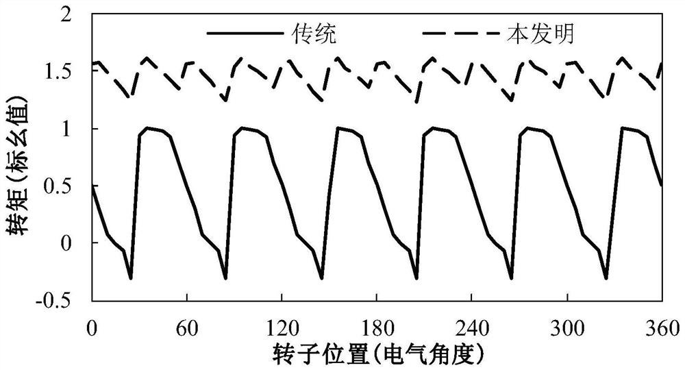
In contrast, using a sinusoidal current to drive the motor is beneficial to reduce vibration and noise, but simply replacing the unipolar square wave current of the traditional switched reluctance motor with a sinusoidal current will seriously weaken the motor torque capability and reduce the motor torque density
On the other hand, the power converter based on the asymmetrical half-bridge circuit topology used with the switched reluctance motor is not common, which also brings obstacles to the large-scale promotion of this type of motor

Method used


Image

  • Ring winding reluctance motor, system and control method thereof
  • Ring winding reluctance motor, system and control method thereof
  • Ring winding reluctance motor, system and control method thereof

Examples


Embodiment 1

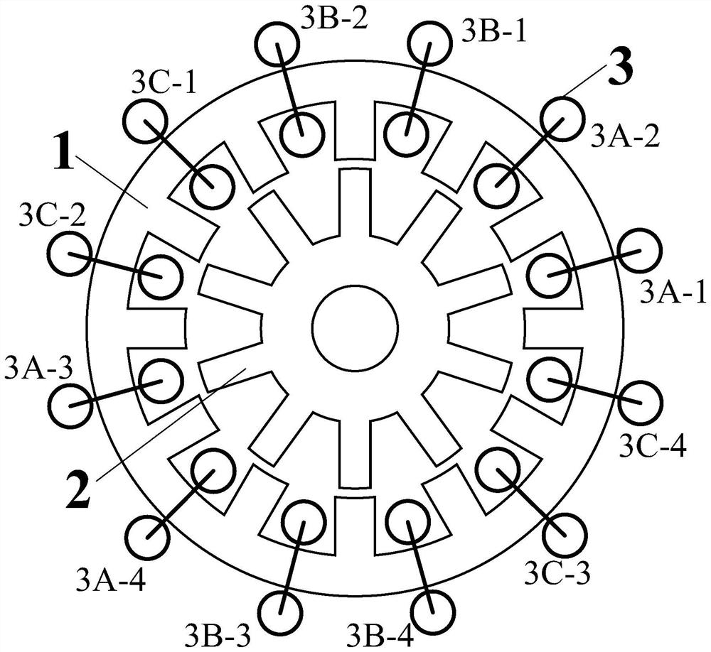
[0043] figure 1 It is a schematic cross-sectional structure schematic diagram of a ring-winding reluctance motor in an embodiment of the present invention.

[0044] Such as figure 1As shown, in this embodiment, the ring-winding reluctance motor is a radial magnetic field rotating motor with an inner rotor structure. The stator has twelve slots, the rotor has ten poles, and the armature winding has three phases and contains twelve armature winding coils.

[0045] Specifically, it includes a stator core 1, a rotor core 2, and an armature winding 3. Wherein, the rotor core 2 is located inside the stator core 1 to form an inner rotor structure (of course, in some other embodiments, it can also be made into an outer rotor structure, that is, the rotor core 2 is located outside the stator core 1). Both the stator core 1 and the rotor core 2 can be made by laminating silicon steel punching sheets.

[0046] further reference figure 1 It can be seen that the armature winding 3 inc...

Embodiment 2

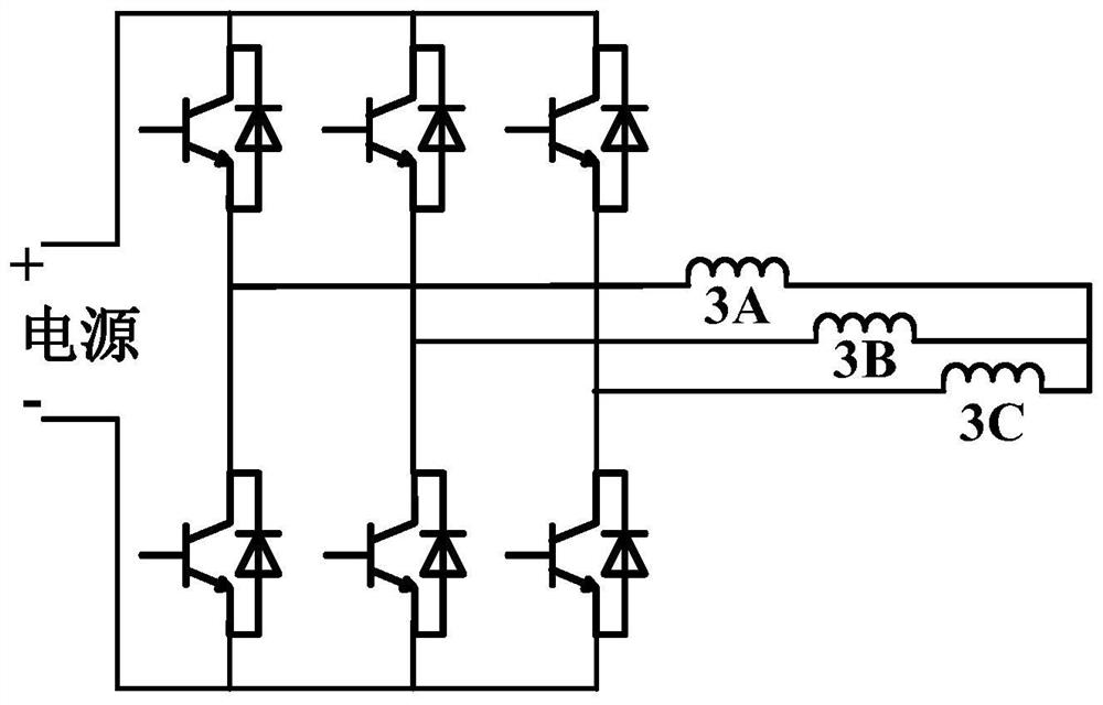
[0052] The structure of the toroidal winding reluctance motor system in embodiment 2 is basically the same as that of the toroidal winding reluctance motor system in embodiment 1, the difference being that the number of stator slots of the toroidal winding reluctance motor in embodiment 2 is six 1. The number of rotor poles is five, correspondingly, the armature winding 3 of the motor includes six armature winding coils, forming a symmetrical three-phase winding. It should be pointed out that, similar to Embodiment 1, in Embodiment 2, the armature winding 3 is electrically connected to the power converter based on the three-phase full-bridge circuit topology, and then the three-phase symmetrical sinusoidal current is loaded to realize the stable operation of the motor .


PUM


Abstract

The invention provides an annular winding reluctance motor, a system and a control method thereof. The annular winding reluctance motor comprises a stator iron core, a rotor iron core and an armature winding, wherein the stator iron core and the rotor iron core are concentrically arranged; the armature winding is placed on the stator iron core, and a coil of the armature winding adopts an annular winding structure with non-overlapped end parts and is nested in a yoke part of the stator iron core; the stator iron core and the rotor iron core are both of a salient pole structure and are provided with salient pole teeth facing the air gap side, the number of the stator salient pole teeth is not equal to the number of the rotor salient pole teeth, and the number of the rotor salient pole teeth is an odd number or an even number. According to the ring winding reluctance motor, through flexible fusion of winding forms and innovation of the number of salient pole teeth of the rotor, optimal adaptation of sine armature current can be realized, and the motor has the advantages of high torque density, low torque pulsation and low vibration noise.

Description

technical field [0001] The invention relates to the field of motor equipment, in particular to a switched reluctance motor, a system and a control method thereof. In particular, it relates to a ring-winding switched reluctance motor driven by a sinusoidal current. Background technique [0002] With the development of power electronics technology, microelectronics technology and automatic control technology, there are more and more applications of switched reluctance motors. A typical switched reluctance motor has a double-salient stator and rotor structure. There is an armature winding on the stator, but there is neither winding nor permanent magnet on the rotor. The armature winding coil is a concentrated winding structure with short ends and compact structure; the motor cooperates The asymmetrical half-bridge circuit completes electromechanical energy conversion by loading a unipolar square wave current. The switched reluctance motor has simple structure, strong robustne...

Claims


Application Information

Patent Timeline
Patent Type & Authority Applications(China)
IPC IPC(8): H02K3/52H02K1/14H02K1/24H02K1/16H02K16/02H02K16/04
CPCH02K3/522H02K1/14H02K1/24H02K1/16H02K16/02H02K16/04
Inventor 华浩王勇
Owner SHANGHAI JIAO TONG UNIV
Learn More