
Energy echelon multi-stage utilization system of waste incineration power generation dual-pressure boiler

A waste incineration and boiler technology, which is applied in the field of energy cascade and multi-level utilization systems of waste incineration power generation double-pressure boilers, can solve the problems of low requirements for waste heat utilization efficiency, difficulty in waste heat utilization efficiency, and lack of too much emphasis on waste heat utilization of waste incineration. , to achieve the effect of improving the utilization efficiency of waste heat, providing energy utilization rate, and improving the cascade utilization of high and low grade heat sources.

Pending Publication Date: 2022-05-17
BEIJING GEOENVIRON ENG & TECH
View PDF0 Cites 0 Cited by
  • Summary
  • Abstract
  • Description
  • Claims
  • Application Information

AI Technical Summary

Problems solved by technology

[0003] At present, most of the domestic waste incineration industry focuses on how to better and harmlessly dispose of urban domestic waste to avoid adverse effects on the surrounding environment; while there is not much emphasis on the utilization of waste heat from waste incineration, and it is in a relatively extensive operation mode In the process, the requirements for waste heat utilization efficiency are not high, and there is no special and in-depth study on how to improve the waste heat utilization rate of waste incineration, and there is no in-depth investigation on the path technology to improve waste heat utilization efficiency.
[0004] At present, most domestic waste incineration enterprises use the process form of single-pressure waste heat boiler with condensing steam turbine to utilize the waste heat generated by incinerating domestic waste. It is characterized by a simple system and a single process flow; Therefore, expanding the multi-level utilization of energy is a process channel for improving energy utilization

Method used


Image

  • Energy echelon multi-stage utilization system of waste incineration power generation dual-pressure boiler

Examples


Embodiment Construction

[0029] In order to make the purpose, technical solutions and advantages of the embodiments of the present invention clearer, the technical solutions in the embodiments of the present invention will be clearly and completely described below in conjunction with the drawings in the embodiments of the present invention. Obviously, the described embodiments It is a part of embodiments of the present invention, but not all embodiments. Based on the embodiments of the present invention, all other embodiments obtained by persons of ordinary skill in the art without making creative efforts belong to the protection scope of the present invention.

[0030] Below in conjunction with accompanying drawing, the present invention is described in further detail:

[0031] In recent years, with the improvement of people's living standards, the calorific value of the generated domestic waste is also continuously increasing. Therefore, different regions, different seasons, and different times caus...


PUM


Abstract

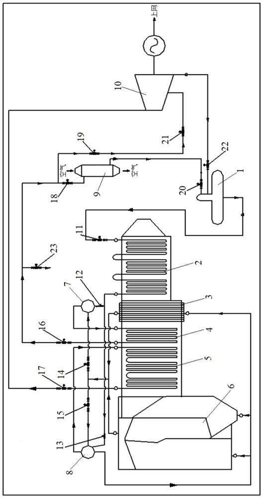
The invention discloses a waste incineration power generation dual-pressure boiler energy echelon multi-stage utilization system which comprises a deaerator, a dual-pressure waste heat boiler, a steam preheater and a steam turbine generator. An outlet of an oxygen device of the dual-pressure waste heat removal boiler is connected with an inlet of a coal economizer, and an outlet of the coal economizer is connected with first inlets of a steam pocket I and a steam pocket II. A first outlet of the steam pocket II is respectively connected with inlets of the water-cooled wall and the evaporator, and outlets of the water-cooled wall and the evaporator are respectively connected with second inlets of the steam pocket I and the steam pocket II after being converged; an outlet of the steam pocket I is connected with an inlet of the superheater I; an outlet of the superheater I is connected with an inlet of the steam preheater; a second outlet of the steam pocket II is connected with an inlet of the superheater II, and an outlet of the superheater II is connected with an inlet of the steam turbine generator; and the outlets of the steam preheater and the steam turbine generator are connected with the inlet of the deaerator. According to the invention, multi-echelon configuration of waste heat and accurate matching of energy are realized, so that the utilization rate of system energy is improved.

Description

technical field [0001] The invention relates to the technical field of utilization of waste heat from waste incineration, in particular to a cascade multi-stage energy utilization system of a double-pressure boiler for power generation by waste incineration. Background technique [0002] Waste incineration power plant is a professional processing enterprise specializing in waste treatment and energy utilization. Urban domestic waste is incinerated to produce hot flue gas, which is then discharged to meet the standard after heat exchange and cooling by waste heat boiler. The use of heat generated by waste incineration is also the focus of the country and the industry. one. [0003] At present, most of the domestic waste incineration industry focuses on how to better and harmlessly dispose of urban domestic waste to avoid adverse effects on the surrounding environment; while there is not much emphasis on the utilization of waste heat from waste incineration, and it is in a rel...

Claims


Application Information

Patent Timeline
Patent Type & Authority Applications(China)
IPC IPC(8): F23G5/46F22B1/18F22B31/08F22D1/50F01K27/00F01D15/10
CPCF23G5/46F22B1/18F22B31/08F22D1/50F01K27/00F01D15/10F23G2206/203Y02E20/12
Inventor 田小辉成斌康宵刘超
Owner BEIJING GEOENVIRON ENG & TECH
Learn More