Unlock instant, AI-driven research and patent intelligence for your innovation.

State switching circuit, photoelectric detection array and optical detection system

A state switching, photoelectric detection technology, applied in radio wave measurement systems, instruments, etc., can solve the problems of complex circuit technology and structure, limited voltage range, high power consumption, etc., to optimize circuit area and power consumption, improve filling factor, the effect of reducing power consumption

Pending Publication Date: 2022-05-20
HESAI TECH CO LTD
View PDF0 Cites 0 Cited by
  • Summary
  • Abstract
  • Description
  • Claims
  • Application Information

AI Technical Summary

Problems solved by technology

However, the current voltage switching circuit has problems such as large power consumption, large area, limited voltage range, complex circuit technology and structure, etc.

Method used


Image

  • State switching circuit, photoelectric detection array and optical detection system
  • State switching circuit, photoelectric detection array and optical detection system
  • State switching circuit, photoelectric detection array and optical detection system

Examples


Embodiment Construction

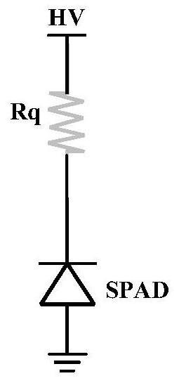
[0057] As mentioned above, single photon avalanche diode (SPAD) is a photodetector widely used in light intensity detection, laser ranging and other fields. Such as figure 1 Shown is a schematic diagram of the circuit structure of a photodetector realized by SPAD in an example. It should be noted that this circuit structure is only a simple illustration, and does not limit the circuit structure of SPAD to strictly follow this figure 1 In actual scenarios, it may be implemented in combination with quenching circuits, recovery circuits, etc., and is not limited to the illustrations.

[0058] From figure 1 It can be seen that the power supply terminal at the top is connected to the high voltage power supply HV, the power supply terminal is coupled to one end of the resistor Rq, the other end of Rq is coupled to the anode of the SPAD, and the cathode of the SPAD is coupled to the ground terminal VSS. When the SPAD is selected, the HV is connected, and the HV is higher than the ...


PUM


Abstract

The invention provides a state switching circuit, a photoelectric detection array and an optical detection system, and the state switching circuit comprises a resistor voltage division circuit which leads out a first output end at at least one voltage division point between resistors in a line between a voltage supply end and a grounding end; the resistance voltage division circuit comprises at least one first controllable switch located in the circuit, and the first controllable switch is used for being in a corresponding on-off state according to a received external control signal and an access voltage so as to form a voltage division signal at the first output end; and a second controllable switch of the voltage output circuit is coupled to the first output end and is used for being in a corresponding switching state according to the voltage supplied by the power supply end and the voltage division signal so as to control the output of a second output end and outputting a state switching signal to a photoelectric detector coupled to the second output end so as to control the working state of the photoelectric detector. According to the scheme, static power consumption can be reduced, the circuit structure can be simplified in cooperation with an optimization scheme, and the circuit area and power consumption are optimized.

Description

technical field [0001] The embodiments of the present application relate to the technical field of optical detection equipment, and in particular, to a state switching circuit, a photoelectric detection array, and an optical detection system. Background technique [0002] LiDAR is a sensor that uses laser light to achieve precise distance measurement. LiDAR emits pulses of laser light that bounce off surrounding objects, and by measuring the time it takes for the laser light to reach each object and return to it, the precise distance of the object can be calculated. Lidar emits multiple pulses per second, and by collecting these distance measurements and monitoring the bearings from which the pulses are sent and received, a three-dimensional model of the environment, known as a point cloud, can be built. [0003] LiDAR has a wide range of applications, including: autonomous driving (self-driving taxis, buses, trucks, logistics vehicles, etc.), map mapping, smart cities / V2X,...

Claims


Application Information

Patent Timeline
IPC IPC(8): G01S7/484
CPCG01S7/484
Inventor 朱文毅王陈銮姚廷宇朱雪洲向少卿
Owner HESAI TECH CO LTD
Features
  • R&D
  • Intellectual Property
  • Life Sciences
  • Materials
  • Tech Scout
  • Unparalleled Data Quality
  • Higher Quality Content
  • 60% Fewer Hallucinations
Learn More