Rotational flow opposite impact type PIV solid particle generator and particle generation method

A solid particle, hedging technology, used in fluid velocity measurement, instruments, combustion engines, etc., can solve problems such as the inability of PIV particle generators, the complex and harsh test environment requirements of supersonic flow fields and combustion fields, and reduce the risk of agglomeration. , Improve operability, enhance the effect of shear force

Pending Publication Date: 2022-05-24
中国空气动力研究与发展中心设备设计与测试技术研究所
View PDF2 Cites 2 Cited by
  • Summary
  • Abstract
  • Description
  • Claims
  • Application Information

AI Technical Summary

Problems solved by technology

[0006] The present invention provides a swirling flow counter type PIV solid particle generator and a particle generating method to solve the problem that the PIV particle generator in the prior art cannot meet the complex and harsh test environment requirements in the supersonic flow field and the combustion field, and realize the improvement of the particle size. The purpose of fluidization effect, reducing the probability of particle agglomeration and easy disassembly and cleaning

Method used


Image

  • Rotational flow opposite impact type PIV solid particle generator and particle generation method
  • Rotational flow opposite impact type PIV solid particle generator and particle generation method
  • Rotational flow opposite impact type PIV solid particle generator and particle generation method

Examples


Embodiment 1

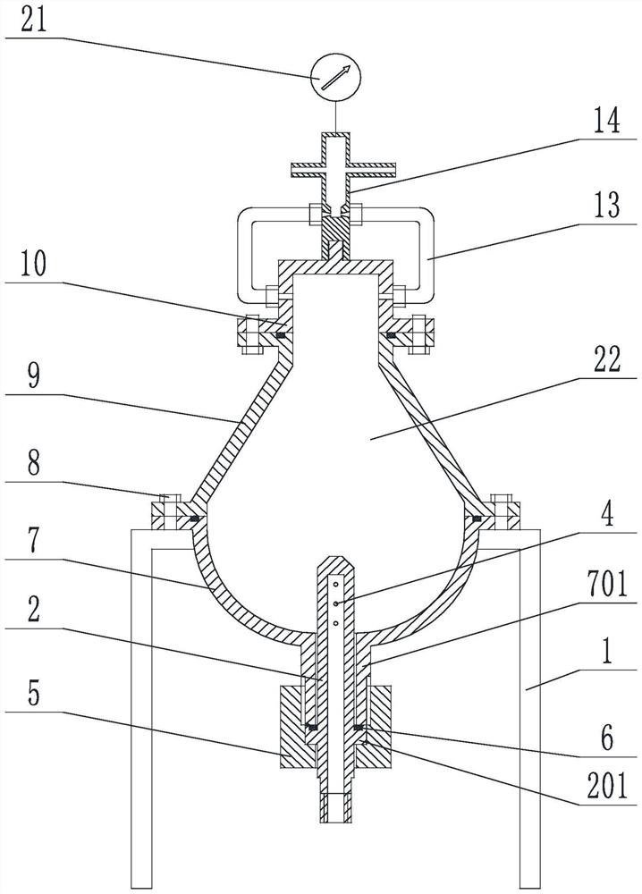
[0047] as Figure 1 A swirl hedging type PIV solid particle generator shown, comprising a swirl chamber 22, an intake nozzle 2 and a particle hedging tube 14 communicated with the swirl chamber 22, the swirl chamber 22 is successively removable connected arc bottom member 7, a closed middlepart 9, a concave top member 10 around; the particle hedging tube 14 is provided with a total outlet 19;

[0048] The concave side of the curved bottom member 7 is facing upwards, the inner diameter of the closing type middlepart 9 is gradually reduced from the bottom to the top, and the concave side of the concave top member 10 is facing down;

[0049] The intake nozzle 2 is inserted from the arc bottom member 7 into the swirl chamber 22, and the particle hedging tube 14 is connected to the concave top member 10.

[0050]In the present embodiment, between the curved bottom member 7 and the closing middleware 9, the closing middleware 9 and the concave top member 10, are removablely connected by ...

Embodiment 2

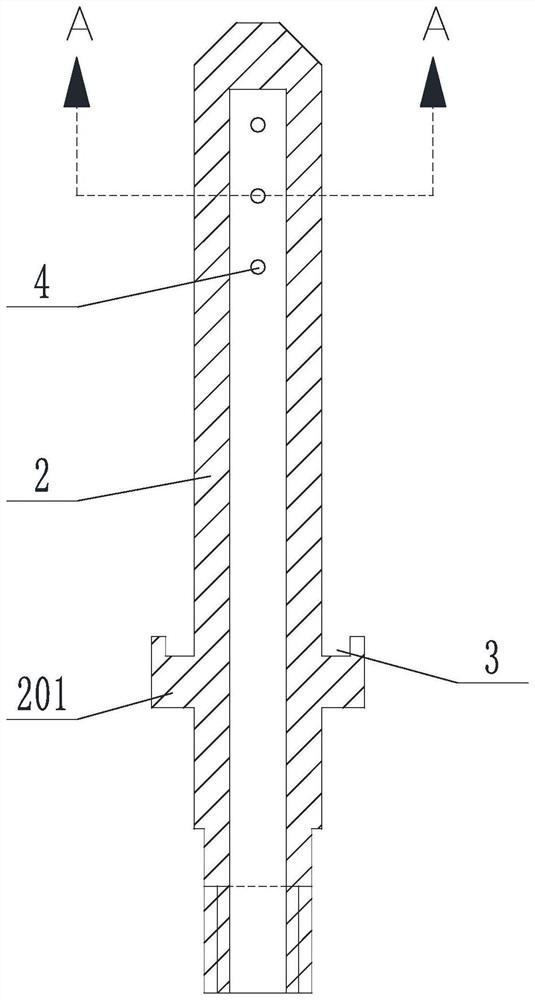
[0053] A swirling hedging PIV solid particle generator, on the basis of Example 1, the arc base member 7 bottom end is provided with a downward extension of the first extension 701, the intake nozzle 2 outer wall is provided with a radial extension of the second extension 201; the intake nozzle 2 through the first extension 701 is inserted into the spiral cavity 22, and the second extension 201 can not enter the first extension 701; further comprising an annular groove 3 located on the upper surface of the second extension 201, the annular groove 3 for assembling the sealing ring 6 Between the intake nozzle 2 and the first extension 701 is detachable by screw sleeve 5.

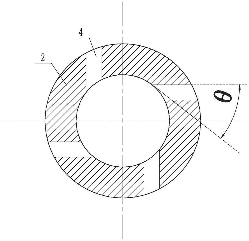
[0054] Where, for example Figure 2 As shown, the intake nozzle 2 is inserted into one end of the cyclone chamber 22 is provided with three sets of exhaust components distributed along the axial direction; the exhaust assembly consists of four cyclic swirl holes 4, and the vortex hole 4 has a diameter of 0.5 to 1 m...

Embodiment 3

[0057] A swirl hedging type PIV solid particle generator, on the basis of any of the above embodiments, such as Figure 5 As shown, the particle hedging tube 14 includes two opposingly distributed hedging inlets 16, each of which is connected to the concave top member 10 via a gas outlet 13.

[0058] Particle hedging tube 14 comprises a first cylindrical cavity 17, the expansion chamber 23, the second cylindrical cavity 24, the inner diameter of the first cylindrical cavity 17 is less than the inner diameter of the second cylindrical cavity 24, the expansion chamber 23 from one end close to the first cylindrical cavity 17 to the inner diameter of one end near the second cylindrical cavity 24 gradually increased; the first cylindrical cavity 17 is closed at the bottom, the hedge inlet 16 is disposed on the side of the first cylindrical cavity 17, and the outlet end of the hedging inlet 16 is constricted.

[0059]The total outlet 19 is disposed on the side of the second cylindrical c...


PUM


Abstract

The invention discloses a rotational flow hedging type PIV solid particle generator and a particle generation method, the generator comprises a rotational flow cavity, an air inlet spray pipe and a particle hedging pipe, the air inlet spray pipe and the particle hedging pipe are communicated with the rotational flow cavity, and the rotational flow cavity is formed by surrounding an arc-shaped bottom piece, a closing-in type middle piece and a concave top piece which are detachably connected in sequence; a total air outlet is formed in the particle hedging pipe; the concave surface of the arc-shaped bottom piece faces upwards, the inner diameter of the necking-in type middle piece is gradually reduced from bottom to top, and the concave surface of the concave top piece faces downwards; the air inlet spray pipe is inserted into the rotational flow cavity from the arc-shaped bottom piece, and the particle hedging pipe is communicated into the concave top piece. The PIV particle generator is used for solving the problem that in the prior art, a PIV particle generator cannot meet the requirement of a complex and severe testing environment in a supersonic flow field and a combustion field, and the purposes of improving the particle fluidization effect, reducing the probability of particle agglomeration and piling and being convenient to disassemble and clean are achieved.

Description

Technical field [0001] The present invention relates to the field of particle tracing laser measurement, specifically to a swirl hedging PIV solid particle generator and particle generation method. Background [0002] PIV technology is a common method for measuring velocity field, which works by: pulsed laser sheet light illumination spreads tracer particles in the flow field, through two or more consecutive exposures, and simultaneously record the image of the particle with the CCD camera, and process the image recorded by the CCD camera through the algorithm, so as to obtain the velocity distribution of the flow field. [0003] The harsh test environment of high pressure and high Mach number in the supersonic flow field and combustion field brings great challenges to PIV velocimetry technology. In PIV experiments, in order to correctly reflect the flow field, it is first necessary to ensure that the tracer particles have good flow following, that is, to reduce the particle size...

Claims


Application Information

Patent Timeline
Patent Type & Authority Applications(China)
IPC IPC(8): G01P5/26G01P1/00
CPCG01P5/26G01P1/00Y02T10/12
Inventor 车庆丰周全张俊陈力陈爽
Owner 中国空气动力研究与发展中心设备设计与测试技术研究所
Why Eureka
Try Eureka