
Simulation system of steam generator heat transfer tube detection robot

A steam generator and simulation system technology, which is applied in the field of simulation systems, can solve problems such as costing a lot of manpower and material resources, equipment damage, and unconfigured robot simulation systems, and achieve the effects of saving manpower and material resources, improving work efficiency, and being simple and convenient

Pending Publication Date: 2022-05-27
STATE NUCLEAR POWER PLANT SERVICE
View PDF0 Cites 0 Cited by
  • Summary
  • Abstract
  • Description
  • Claims
  • Application Information

AI Technical Summary

Problems solved by technology

[0003] In the prior art, in the detection system of steam generator heat transfer tubes, the commonly used detection robot equipment includes the ROSA manipulator of the Westinghouse Company of the United States, the PEGASYS pusher, the ZR100 pusher developed by the US ZETEC company, etc., but the above detection robot equipment No robot simulation system is configured, and the actual inspection robot is often used to debug the inspection robot equipment in the field work, so there are the following defects:
[0004] (1) It takes a lot of manpower and material resources;
[0005] (2) It is easy to cause equipment damage and damage to the heat transfer tube sheet of the steam generator due to unfamiliarity with the site environment;
[0006] (3) In the actual steam generator, the function debugging and performance testing of the steam generator detection robot system cannot be encountered in various possible failure situations, and the function of the steam generator detection robot cannot be comprehensively inspected

Method used


Image

  • Simulation system of steam generator heat transfer tube detection robot
  • Simulation system of steam generator heat transfer tube detection robot
  • Simulation system of steam generator heat transfer tube detection robot

Examples


Embodiment Construction

[0033] The embodiments of the present invention are described below by specific embodiments, and those skilled in the art can easily understand other advantages and effects of the present invention from the contents disclosed in this specification.

[0034] It should be noted that the structures, proportions, sizes, etc. shown in the drawings in this specification are only used to cooperate with the contents disclosed in the specification, so as to be understood and read by those who are familiar with the technology, and are not used to limit the implementation of the present invention. Restricted conditions, it does not have technical substantive significance, any modification of structure, change of proportional relationship or adjustment of size, without affecting the effect that the present invention can produce and the purpose that can be achieved, should still fall within the present invention. The disclosed technical content must be within the scope of coverage. At the ...


PUM


Abstract

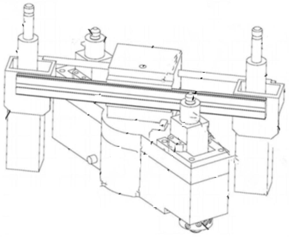
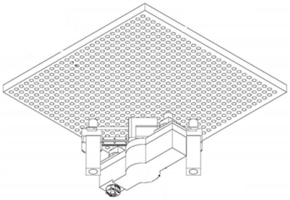
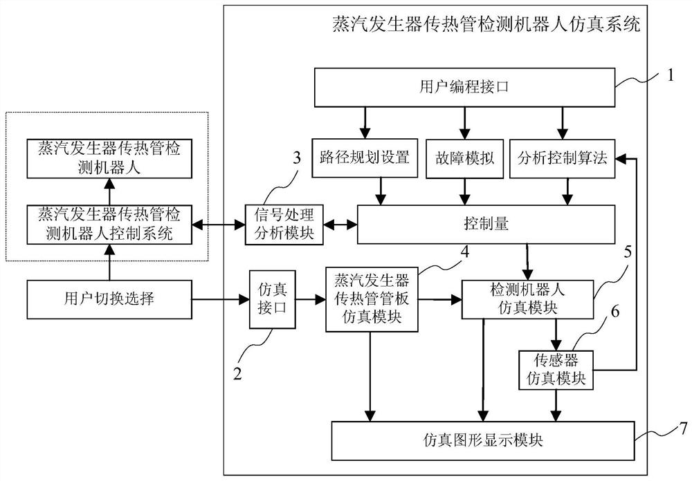
The invention provides a steam generator heat transfer tube detection robot simulation system. The steam generator heat transfer tube detection robot simulation system comprises a user programming interface used for initializing programming and importing and inputting simulation parameters; the simulation interface is used for realizing connection with a detection robot control system; the signal processing and analyzing module is used for realizing data interaction control of the detection robot simulation system and the detection robot control system; the steam generator heat transfer tube plate simulation module is used for realizing simulation of a steam generator heat transfer tube plate structure and space coordinates; the detection robot simulation module is used for realizing simulation of functions and performance of the steam generator heat transfer tube detection robot; the sensor simulation module is used for realizing motion simulation of the detection robot; and the simulation graph display module is used for realizing real-time simulation graph display. The simulation system of the steam generator heat transfer tube detection robot can simulate function debugging and performance testing of the steam generator heat transfer tube detection robot, manpower and material resources are saved, and the working efficiency is improved.

Description

technical field [0001] The invention relates to a simulation system, in particular to a robot simulation system for detecting a heat transfer tube of a steam generator. Background technique [0002] The steam generator of AP1000 nuclear power plant is equipped with tens of thousands of thin-walled heat transfer tubes, which are arranged in a triangular or square arrangement. The steam generator heat transfer tube is the pressure boundary between the primary side and the secondary side of the nuclear power plant. Under the action of water flow and long-term alternating stress of high temperature and high pressure, the heat transfer tubes will have defects such as thinning, wear, pits, stress corrosion, and intergranular corrosion during the operation of nuclear power plants. leakage, causing radioactive contamination of the secondary circuit. Therefore, the inspection of heat transfer tubes in nuclear power plants is a mandatory inspection item during the annual refueling o...

Claims


Application Information

Patent Timeline
IPC IPC(8): G05B17/02
CPCG05B17/02Y02E30/30
Inventor 孙茂荣赵琛陶泽勇郑楚悦程保良赵晓敏田野张益王一帆沈杰郑怡廷李思颖
Owner STATE NUCLEAR POWER PLANT SERVICE
Learn More