Compact range device based on microstrip patch reflective array antenna

A reflect array antenna, microstrip patch technology, applied to antennas, measuring devices, antenna arrays, etc., can solve the problems of high processing cost, difficult lens material processing, increasing paraboloid size, etc., and achieve manufacturing costs and maintenance costs. Low, improve the quality of plane wave quiet zone, the effect of mature and simple process

Pending Publication Date: 2022-05-31
XIDIAN UNIV
View PDF0 Cites 3 Cited by
  • Summary
  • Abstract
  • Description
  • Claims
  • Application Information

AI Technical Summary

Problems solved by technology

[0003] The existing compact field system can be divided into reflective compact field and lens compact field according to the form of the conversion unit. Among them, the utilization rate of the quiet zone of the single parabolic compact field in the reflective compact field is low, and the paraboloid needs to be enlarged when measuring large-diameter antennas. The size and processing cost are expensive, which greatly increases the production cost; the lens material processing is difficult in the lens-type compact field, and the uniformity of the lens is difficult to guarantee
[0004] In summary, the parabolic antenna used in the existing reflective compact field system is large in size and high in cost; the lens material used in the transmissive compact field system is difficult to process, resulting in poor lens uniformity, which is difficult to apply to low-cost scenarios

Method used


Image

  • Compact range device based on microstrip patch reflective array antenna
  • Compact range device based on microstrip patch reflective array antenna
  • Compact range device based on microstrip patch reflective array antenna

Examples


example

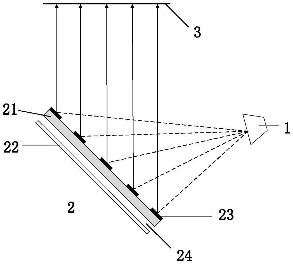
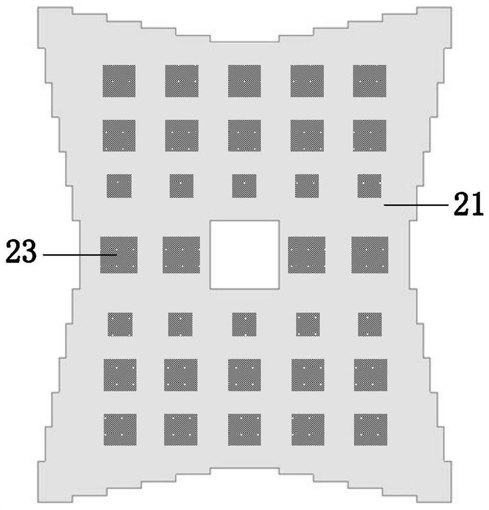
[0037] refer to image 3 In the system structure shown, the feed source is a pyramid horn, and the feed method adopts a bias feed; the center frequency of the microstrip patch reflectarray antenna is set to 10GHz, the unit interval is one-third wavelength, and the focal-to-diameter ratio F / D is 1.8, and the edge of the dielectric plate of the microstrip patch reflectarray antenna is processed in a step-like manner, and the center of the dielectric plate is set as an empty area to reduce the number of patch units of the reflector and optimize the exit field quiet zone.

[0038] 2. Simulation content:

[0039] In the above example, the spherical wave irradiated by the feed source is converted into a plane wave by the microstrip patch reflectarray antenna, and the phases of the reflectarray units with different side lengths corresponding to different air layer thicknesses are simulated to obtain the phase shift curves of the reflector units, such as Image 6 shown. Depend on ...


PUM


Abstract

The invention relates to a compact range device based on a microstrip patch reflective array. The compact range device mainly solves the problems that an existing reflective compact range device is high in cost and large in machining difficulty. The antenna comprises a feed source (1) and a microstrip patch reflective array antenna (2), the feed source adopts a horn antenna and is located above one side of an aperture of the microstrip patch reflective array antenna to emit spherical electromagnetic waves, the reflective array antenna converts the spherical electromagnetic waves into emergent plane waves, and a plane wave dead zone (3) is formed after the distance between the emergent direction and the aperture of the microstrip patch reflective array antenna is 6 times of the aperture of the microstrip patch reflective array antenna. The microstrip patch reflective array antenna comprises a dielectric plate (21), a metal reflective floor (22) and a plurality of reflective array units (23), the edge of the dielectric plate adopts a stepped structure, all the reflective array units are arranged on the surface of the dielectric plate according to a fixed period, the dielectric plate and the metal reflective floor are arranged in parallel up and down, and an air layer (24) is formed between the dielectric plate and the metal reflective floor. The device is small in size, light in weight, easy to install, low in manufacturing and maintenance cost and capable of being used for low-cost scenes.

Description

technical field [0001] The invention relates to the technical field of antenna measurement, and further relates to a compressed field device, which can be used for high-frequency large-diameter antenna testing. Background technique [0002] The traditional far-field test method requires the transmitting antenna to radiate electromagnetic waves to the antenna under test in the form of plane waves. In order to meet the test requirements, a certain distance is required between the transmitting antenna and the antenna under test, and the distance between the two is proportional to the operating frequency of the antenna. For high-frequency antennas, the requirements of the far-field test site and measurement environment are very demanding and almost difficult to meet. In the 1960s, Johnson et al. of Georgia Institute of Technology announced a single-mirror constricted field measurement system consisting of a parabolic cylinder and a feed, such as figure 1 shown. The compact fie...

Claims


Application Information

Patent Timeline
Patent Type & Authority Applications(China)
IPC IPC(8): G01R29/10G01R1/02H01Q21/06
CPCG01R29/10G01R1/02H01Q21/065
Inventor 翁子彬马铭旭侯鼎田季丰张立焦永昌
Owner XIDIAN UNIV
Why Eureka
Try Eureka