Double-ring radio frequency capacitive coupling discharge plasma enhanced getter device

A discharge plasma, capacitive coupling technology, applied in the direction of plasma, electrical components, separation methods, etc., can solve the problems of slow inhalation rate, low electrothermal conversion efficiency, low applicability, etc., to speed up the inhalation rate, improve The effect of a slow inspiratory rate

Active Publication Date: 2022-06-07
DALIAN INST OF CHEM PHYSICS CHINESE ACAD OF SCI
View PDF8 Cites 0 Cited by
  • Summary
  • Abstract
  • Description
  • Claims
  • Application Information

AI Technical Summary

Problems solved by technology

How to ensure the encapsulation and air absorption of large-volume getters is a technical problem; ②When the getter is activated by heating, its electrothermal conversion efficiency is relatively low, and it usually takes a period of time before the getter can be activated And then to absorb gas to achieve the purpose of obtaining a higher vacuum, especially for the large-volume getter material used in the enlarged industrial device, it may take longer to activate, which leads to not only the energy required for a long time Stable and continuous injection, and it is less suitable for flexible and quick activation of inhalation; ③ The getter is selective for the adsorption of some gases, and the inhalation rate will be greatly affected depending on the type of gas. At the same time, the temperature and time of getter activation are also accompanied by considerable differences. For some gases that are difficult to absorb, such as nitrogen, it often requires a high temperature of several hundred degrees Celsius to activate the getter, and the inspiratory rate after activation How to effectively increase the adsorption rate of quantitative getters for gases that are difficult to adsorb is very important
[0005] The existence of the above problems sometimes limits the comprehensive application functions of getters. It is very important to find a device that can meet the current application requirements of large volume getters and improve the activation time and adsorption rate.

Method used


Image

  • Double-ring radio frequency capacitive coupling discharge plasma enhanced getter device

Examples


Embodiment Construction

[0024] The present invention will be described in further detail below in conjunction with the accompanying drawings.

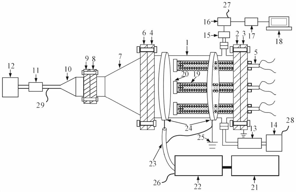
[0025] like figure 1 As shown, the present invention includes a gas supply system 29, a diffuser 7 and a vacuum chamber 1 connected in sequence, wherein a hollow cylinder 19 with holes on the wall is provided in the vacuum chamber 1, and the hollow cylinder 19 with holes on the wall The upper end is sealed, the lower end is open, and the outer wall is sealed and connected to the bottom of the vacuum chamber 1. An electric heating element 5 is arranged in the hollow cylinder 19 with holes on the wall, and the lower end of the electric heating element 5 is connected by the hollow cylinder 19 with holes on the wall. The lower end opening protrudes to the outside of the vacuum chamber 1 and is connected to an external power source. Two ring-shaped single-set parallel electrodes 24 are arranged on the outside of the vacuum chamber 1, and a radio frequency power su...


PUM


Abstract

A hollow cylinder with holes in the wall surface is arranged in a vacuum cavity, the upper end of the hollow cylinder with the holes in the wall surface is sealed, the lower end of the hollow cylinder with the holes in the wall surface is open, the outer wall of the hollow cylinder with the holes in the wall surface is connected with the bottom end of the vacuum cavity in a sealed mode, and an electric heating element is arranged in the hollow cylinder with the holes in the wall surface. The lower end of the electric heating element extends out of the vacuum cavity from an opening in the lower end of the hollow cylinder with the hole in the wall face to be connected with an external power source, two annular single-set parallel electrodes are arranged on the outer side of the vacuum cavity, a radio frequency power supply system is arranged on one side of the vacuum cavity, and the two single-set parallel electrodes are both connected with the radio frequency power supply system. A vacuumizing system is arranged on one side of the bottom end of the vacuum cavity, and an air pressure collecting system is arranged on the other side. The defect of long activation time of a large-volume getter in pure heating is effectively overcome through a heating and radio frequency electromagnetic field coupling mode, and the air suction rate of the getter can be improved and enhanced through plasmas generated by radio frequency discharge.

Description

technical field [0001] The invention relates to the technical field of vacuum adsorption, in particular to a double-ring radio frequency capacitive coupling discharge plasma enhanced getter device. Background technique [0002] At present, industrial applications and basic scientific research in many fields need to be carried out in a vacuum environment, such as coating, heat treatment, micro-electromechanical system, surface science, atomic physics, nanotechnology and semiconductor industry. For vacuum technology, the internal vacuum environment and vacuum degree directly affect the working range and efficiency, especially after entering the 21st century, with the continuous improvement of various application indicators and the deepening of basic discipline research, its operation and research The environment requires different degrees of high vacuum or even ultra-high vacuum to maintain, which also puts forward higher requirements and challenges for the process of vacuum p...

Claims


Application Information

Patent Timeline
IPC IPC(8): B01D53/02H05H1/46
CPCB01D53/02H05H1/46Y02E30/10
Inventor 杨亮李庆伟石文波耿自才李永钊吴克难赵天亮周冬建回晓康金玉奇
Owner DALIAN INST OF CHEM PHYSICS CHINESE ACAD OF SCI
Why Eureka
Try Eureka