Spiral piezoelectric electro-catalysis sewage treatment device and treatment method

A sewage treatment device, electro-photocatalytic system technology, applied in the direction of light water/sewage treatment, water/sewage treatment, water/sewage treatment equipment, etc., can solve high-frequency ultrasonic input energy consumption, easy settlement, low utilization rate, etc. problems, to achieve the effect of extending the length of the pipeline, prolonging the reaction time, and simplifying the structure of the device

Pending Publication Date: 2022-06-07
HOHAI UNIV
View PDF5 Cites 0 Cited by
  • Summary
  • Abstract
  • Description
  • Claims
  • Application Information

AI Technical Summary

Problems solved by technology

[0002] With the development of society and industrialization, the shortage of fossil energy and environmental pollution have posed serious challenges to the sustainable development of human society and economy; how to use clean and renewable new energy to purify pollutants is the key to ensuring people's lives and health and sustainable social and economic development Among them, solar energy, as an important part of the clean energy industry, has a wide range of applications in photocatalytic degradation of pollutants; nanophotocatalysts use the strong redox properties of photogenerated electron-hole pairs under visible light or ultraviolet light, and are highly efficient , and quickly remove organic pollutants in water; however, nano-photocatalysts have problems such as easy sedimentation, low utilization rate, and difficulty in recycling in actual water restoration. At the same time, due to the low quantum efficiency of semiconductor photocatalysts, semiconductor photocatalytic technology Difficult to achieve large-scale industrial application
[0003]

Method used


Image

  • Spiral piezoelectric electro-catalysis sewage treatment device and treatment method
  • Spiral piezoelectric electro-catalysis sewage treatment device and treatment method
  • Spiral piezoelectric electro-catalysis sewage treatment device and treatment method

Examples


Example Embodiment

[0055] Example 1

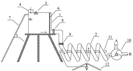
[0056] A spiral piezoelectric photocatalytic sewage treatment device, the structure of which includes a water inlet system and a spiral piezoelectric photocatalytic system;

[0057] The water inlet system includes a water tank 1 , a support table 3 , a water inlet 4 , an exhaust valve 5 , a maintenance ladder 7 , and a water level detector 6 .

[0058] The water tank 1 is placed above the support table 3; there is a water inlet 4 on the top of the water tank 1, and the sewage to be treated is transported to the water tank 1 through the water inlet 4; an exhaust valve 5 is arranged above the water tank to adjust the inside of the box pressure; the maintenance ladder 7 is located on the side of the water tank 1 and is used for daily inspection and maintenance; the water tank 1 is provided with a water level detector 6 to detect the water level in the water tank in real time.

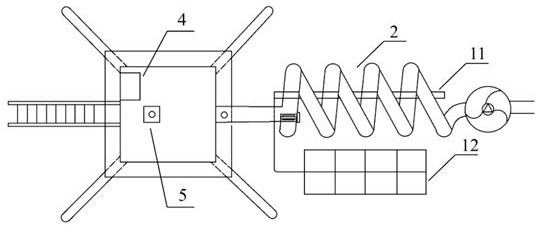
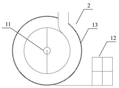
[0059] The spiral piezoelectric photocatalytic system includes a spiral pipeline 2 ...

Example Embodiment

[0061] Example 2

[0062] A spiral piezoelectric photocatalytic sewage treatment device, the structure of which includes a water inlet system and a spiral piezoelectric photocatalytic system;

[0063] The water inlet system includes a water tank 1 , a support table 3 , a water inlet 4 , an exhaust valve 5 , a maintenance ladder 7 , and a water level detector 6 .

[0064] The water tank 1 is placed above the support table 3; there is a water inlet 4 on the top of the water tank 1, and the sewage to be treated is transported to the water tank 1 through the water inlet 4; an exhaust valve 5 is arranged above the water tank to adjust the inside of the box pressure; the maintenance ladder 7 is located on the side of the water tank 1 and is used for daily inspection and maintenance; the water tank 1 is provided with a water level detector 6 to detect the water level in the water tank in real time.

[0065] The spiral piezoelectric photocatalytic system includes a spiral pipeline 2 ...

Example Embodiment

[0067] Example 3

[0068] A spiral piezoelectric photocatalytic sewage treatment device, the structure of which includes a water inlet system and a spiral piezoelectric photocatalytic system;

[0069] The water inlet system includes a water tank 1 , a support table 3 , a water inlet 4 , an exhaust valve 5 , a maintenance ladder 7 , and a water level detector 6 .

[0070] The water tank 1 is placed above the support table 3; there is a water inlet 4 on the top of the water tank 1, and the sewage to be treated is transported to the water tank 1 through the water inlet 4; an exhaust valve 5 is arranged above the water tank to adjust the inside of the box pressure; the maintenance ladder 7 is located on the side of the water tank 1 and is used for daily inspection and maintenance; the water tank 1 is provided with a water level detector 6 to detect the water level in the water tank in real time.

[0071] The spiral piezoelectric photocatalytic system includes a spiral pipeline 2 ...


PUM


Abstract

The invention provides a spiral piezoelectric electro-catalysis sewage treatment device. The spiral piezoelectric electro-catalysis sewage treatment device structurally comprises a water inlet system and a spiral piezoelectric electro-catalysis system, the spiral piezoelectric electro-catalysis system comprises a spiral pipeline and a piezoelectric film; a water outlet of the water inlet system communicates with a water inlet of the spiral pipeline, and the piezoelectric film is located in the spiral pipeline. A method for sewage treatment by using the spiral piezoelectric electro-catalysis sewage treatment device comprises the following steps: 1, sewage and wastewater enter the water tank through a water inlet of the water inlet system, are regulated to a proper flow speed through the flow regulating valve, and enter the spiral pipeline; 2, sewage and wastewater pass through the spiral pipeline under the action of gravitational potential energy, and the sewage and wastewater are in full contact with the piezoelectric film in the spiral pipeline; and 3, under the irradiation of an ultraviolet lamp tube, carrying out photocatalytic degradation reaction on the photocatalytic material on the piezoelectric film and pollutants in the sewage and wastewater. The piezoelectric effect of the material is excited by utilizing water flow potential energy, and the device has the advantages of energy conservation, environmental protection and easiness in implementation.

Description

technical field [0001] The invention relates to a spiral piezoelectric photocatalytic sewage treatment device and a treatment method, belonging to the field of water pollution control. Background technique [0002] With the development of society and industrialization, the shortage of fossil energy and environmental pollution have posed a serious challenge to the sustainable development of human society and economy; how to use clean and renewable new energy to purify pollutants is to ensure people's health and sustainable social and economic development. Among them, solar energy, as an important part of the clean energy industry, has broad applications in photocatalytic degradation of pollutants; nano-photocatalysts utilize the strong redox properties of photogenerated electron-hole pairs under visible light or ultraviolet light, and are highly efficient , Rapidly remove organic pollutants in water bodies; however, nano-photocatalysts have problems such as easy sedimentation...

Claims


Application Information

Patent Timeline
IPC IPC(8): C02F1/32
CPCC02F1/32C02F2201/002C02F2201/009Y02W10/37
Inventor 敖燕辉温英英车慧楠王沛芳
Owner HOHAI UNIV
Why Eureka
Try Eureka