Supercharge Your Innovation With Domain-Expert AI Agents!

Integrated dehydration process based on high-dryness sludge extrusion device

An extrusion device and high dryness technology, applied in water/sludge/sewage treatment, sludge treatment, chemical instruments and methods, etc., can solve the problems of high production cost, high cost, and inability to achieve overall drying , to achieve the effect of improving extrusion efficiency and increasing efficiency

Pending Publication Date: 2022-06-17
SUZHOU VOCATIONAL UNIV +1
View PDF9 Cites 0 Cited by
  • Summary
  • Abstract
  • Description
  • Claims
  • Application Information

AI Technical Summary

Problems solved by technology

However, after dehydration by the electroosmotic sludge dewatering machine, the upper layer of the sludge is dry and the lower layer is wet, which still cannot achieve the purpose of overall drying and the cost is very high
There is also a patent CN201511015321.X disclosing a high-dryness sewage sludge treatment method, which mainly uses active gas to oxidize the sludge squeezed in the spiral filter device, and then enters the ultra-high voltage electroosmotic dehydration The device dewaters to obtain high-dryness sludge, but the production cost is high and the energy consumption is high
[0004] However, the technical problems solved by the above technical solutions only consider the problem of sludge drying, and the use environment brought about by the dehydration device, the consumption of equipment energy consumption, and the cost of use have not been well coordinated. It is only a short-term means of sludge treatment

Method used


Image

  • Integrated dehydration process based on high-dryness sludge extrusion device
  • Integrated dehydration process based on high-dryness sludge extrusion device
  • Integrated dehydration process based on high-dryness sludge extrusion device

Examples


Embodiment 1

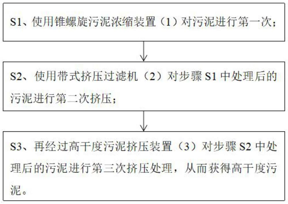
[0060] This example mainly introduces the devices used in the integrated dehydration process based on the high-dryness sludge extrusion device.

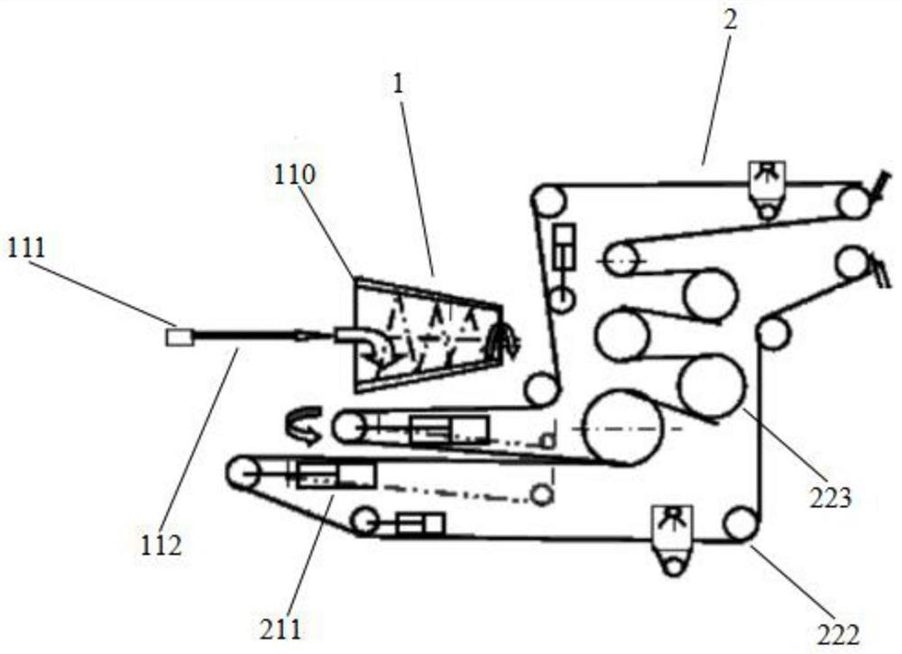
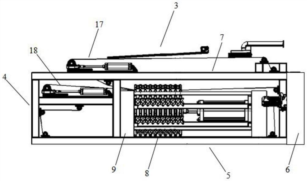
[0061] refer to figure 2 , 3 as shown, figure 2 It is a schematic diagram of the cone-screw sludge thickening device of the present invention, image 3 It is a schematic diagram of the high-dryness sludge extruding device in the present invention. It mainly includes: a cone-screw sludge thickening device 1, a belt extrusion filter 2 and a high-quality sludge extrusion device 3, and the outlet of the cone-screw sludge concentration device 1 is located at the belt extrusion filter 2 The inlet of the belt extrusion filter 2 is located at the inlet of the high-dryness sludge extrusion device 3 .

[0062] Further, the high-dryness sludge extrusion device 3 used in step 3 includes a feed device 4, an extrusion part assembly 5, and a discharge device 6; the feed device 4 is installed on the extrusion part assembly 5 front end, and th...

Embodiment 2

[0085] Based on the foregoing embodiments, this embodiment briefly describes the cone-screw sludge thickening device and the belt squeeze filter in the integrated dehydration process.

[0086] refer to figure 2 as shown, figure 2 It is a schematic diagram of the cone-screw sludge thickening device of the present invention. The cone-screw sludge thickening device 1 used in the step S1 includes a conical shell 110, a fourth rotating motor 111 and a screw 112;

[0087] The round table shell 110 is hollow, and no top cover is provided at both ends. The screw mandrel 112 is located in the round table shell 110. The fourth rotating motor 111 is connected with the screw mandrel 112 through a transmission assembly. The screw mandrel 112 is provided with a continuous The threaded sheet, the pitch of the threaded sheet becomes smaller gradually. As the screw pitch changes from large to small, the extrusion pressure in the cone-screw sludge thickening device 1 increases from small t...

Embodiment 3

[0093] The difference between this embodiment and embodiment 1,2 is:

[0094] Before step S1, a flocculant can also be used to pretreat the sludge for the first time.

[0095] Alternatively, before step S1, a plasma wall-breaking device can also be used to pretreat the sludge, through which the plasma wall-breaking device crushes and shears the sludge, and the plasma generator in the plasma wall-breaking device can also realize Elimination of harmful substances in sludge components and removal of odors in sludge.

[0096] Before step S3, a wide laser intracellular water splitting device can also be used to split the intracellular water of the second squeezed sludge.

[0097] Alternatively, the wide laser intracellular water splitting device can be arranged between the outlet of the belt squeeze filter 2 and the inlet of the belt-type plate and frame ultra-high dryness compressor 3, or between the cone and screw sewage A dehydration treatment is carried out before the mud thi...


PUM


Abstract

The invention discloses an integrated dehydration process based on a high-dryness sludge extrusion device. The integrated dehydration process comprises the following steps: S1, extruding sludge for the first time by using a conical spiral sludge concentration device; s2, carrying out secondary extrusion by using a belt type extrusion filter; and S3, carrying out third extrusion treatment through the high-dryness sludge extrusion device to obtain the high-dryness sludge. By means of the dewatering technological process of the steps S1 to S3, low-energy-consumption and low-cost sludge dewatering treatment is achieved, and the drying rate of the treated sludge reaches 40% or below. According to the high-dryness sludge extrusion device, the movable pressing plate and the sliding pressing plate in the high-dryness sludge extrusion device are arranged to be of a concave-convex extrusion structure, a continuous concave-convex extrusion structure is formed among the multiple continuous extrusion plate assemblies, overflow is avoided, and the extrusion efficiency and the sludge extrusion stability are improved. The variable-pitch stepped sludge concentration device is arranged, and the extrusion pressure in the conical spiral sludge concentration device is increased from small along with the decrease of the pitch, so that the first-time pressure progressive extrusion is realized one by one.

Description

technical field [0001] The invention belongs to the field of sludge extrusion equipment manufacturing and process design, and in particular relates to an integrated dehydration process based on a high-quality sludge extrusion device. Background technique [0002] With the country's strengthening of water pollution control, the problem of sludge disposal has become increasingly apparent and attention has been paid to it. From sludge composting to assisted combustion and landfill. Due to the high moisture content of sludge, large drying energy consumption, and high cost constraints, the treatment effect is not good, and it is easy to cause secondary pollution. Therefore, how to maximize the dehydration efficiency has become the focus of current research. At this stage, sludge dewatering equipment also has disadvantages. At present, the traditional sludge dewatering technology and equipment mainly include belt filter dewatering machines, centrifugal sedimentation filters and p...

Claims


Application Information

Patent Timeline
IPC IPC(8): C02F11/125C02F11/123
CPCC02F11/125C02F11/123
Inventor 芮晓光刘鑫培杨传华朱海明
Owner SUZHOU VOCATIONAL UNIV
Features
  • R&D
  • Intellectual Property
  • Life Sciences
  • Materials
  • Tech Scout
  • Unparalleled Data Quality
  • Higher Quality Content
  • 60% Fewer Hallucinations
Learn More