Point ring laser welding system and method under vacuum condition

A technology of laser welding and vacuum conditions, which is applied in the direction of laser welding equipment, welding equipment, metal processing equipment, etc., can solve the problems of welding quality or penetration ability that cannot be compared with electron beam welding, and achieve the suppression of welding spatter, welding Suppression of slit pores and reduction of tendency to air bubbles

Pending Publication Date: 2022-06-21
哈尔滨工大焊接科技有限公司
View PDF0 Cites 2 Cited by
  • Summary
  • Abstract
  • Description
  • Claims
  • Application Information

AI Technical Summary

Problems solved by technology

[0004] The quality requirements of laser welding in the industry have been continuously improved in recent years. In terms of laser welding of thick plates, laser welding cannot be compared with electron beam welding in terms of welding quality and penetration ability under normal circumstances.

Method used


Image

  • Point ring laser welding system and method under vacuum condition
  • Point ring laser welding system and method under vacuum condition
  • Point ring laser welding system and method under vacuum condition

Examples


Embodiment 1

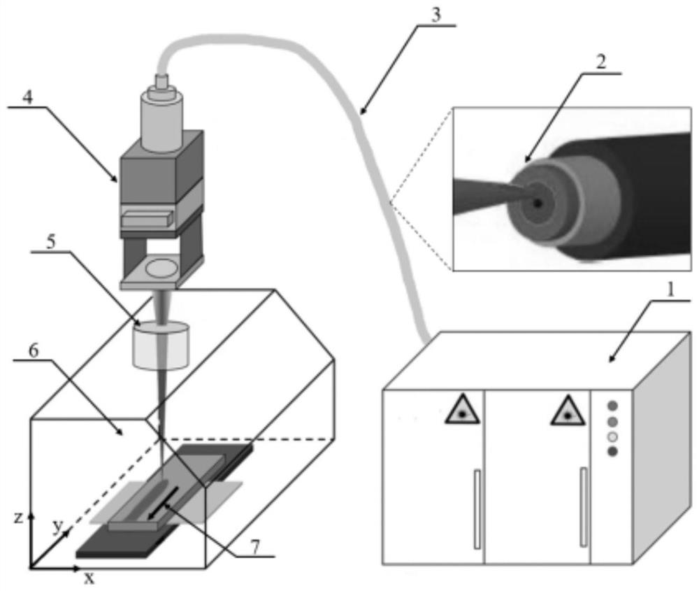
[0048] like figure 1 and Figure 3-Figure 7 As shown, one aspect of the present invention provides a spot-ring laser welding system under vacuum conditions, comprising a solid-state laser 1, a spot-ring laser fiber 3 connected to the solid-state laser 1, and a spot-ring laser fiber 3 disposed on the spot-ring laser fiber 3 away from the The laser processing head 4 at one end of the solid-state laser 1 , the laser coupling window 5 provided under the laser processing head 4 , the vacuum chamber 6 provided under the laser coupling window 5 , and the movement in the vacuum chamber 6 Platform 7; the point-ring laser fiber 3 can directly output a point-ring light source through a single coaxial single fiber, output a point-ring light source through a built-in fiber coupler in the laser, output a point-ring light source through a built-in integrated optical gate of the laser, or output through a two-in-one optical fiber A composite point ring laser beam is formed by various methods...

Embodiment 2

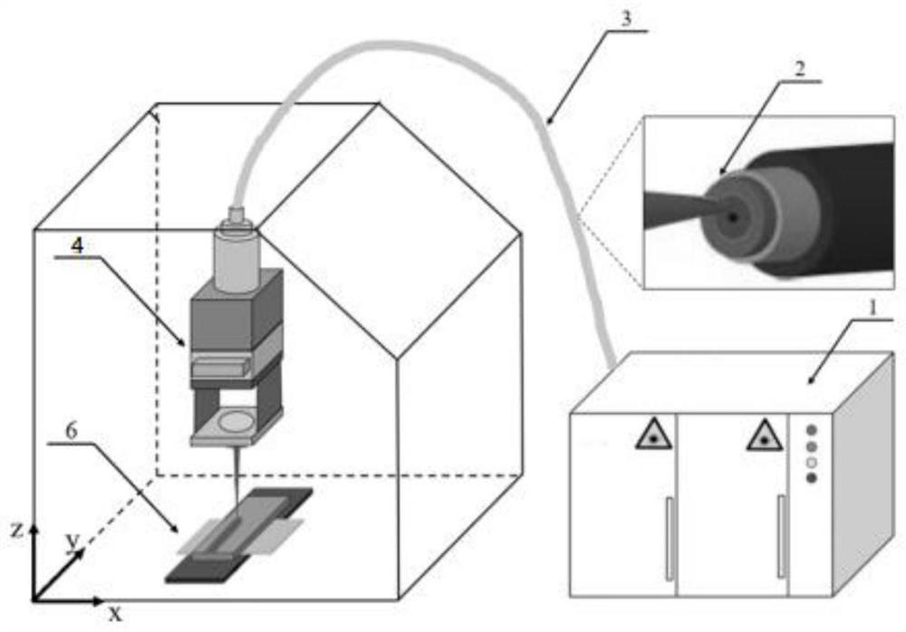
[0053] like Figure 2-Figure 7 As shown, the difference between this embodiment and Embodiment 1 is that the laser processing head of this embodiment is built into the vacuum chamber, and other conditions are the same, as follows:

[0054] An embodiment of the present invention provides a spot-ring laser welding system under vacuum conditions, including a solid-state laser 1, a spot-ring laser fiber 3 connected to the solid-state laser 1, and a spot-ring laser fiber 3 disposed on the spot-ring laser fiber 3 away from the solid state. The laser processing head 4 at one end of the laser 1, the vacuum chamber 6 arranged outside the laser processing head 4, and the mobile platform 7 arranged in the vacuum chamber 6; The solid-state laser 1 emits light, and the laser focused by the laser processing head in the vacuum environment of the vacuum chamber 6 is finally incident on the surface of the welding workpiece to complete the welding process; the point ring laser fiber 3 can pass ...


PUM

PropertyMeasurementUnit
diameteraaaaaaaaaa
diameteraaaaaaaaaa
thicknessaaaaaaaaaa

Abstract

The invention discloses a point-loop laser welding system and method under a vacuum condition. The system comprises a solid laser, a point-loop laser optical fiber connected with the solid laser, a laser processing head and a vacuum cabin which are arranged at the end, away from the solid laser, of the point-loop laser optical fiber, and a moving platform arranged in the vacuum cabin. Light emitted by a solid laser directly outputs a point loop light source through a point loop laser fiber and a coaxial single fiber, outputs the point loop light source through a built-in fiber coupler of the laser, outputs the point loop light source through a built-in integrated optical shutter of the laser or outputs the point loop light source through a two-in-one fiber to form a composite point loop laser beam. The point ring laser power ratio is accurately adjusted according to different welding structure conditions, and the adaptability of point ring laser welding to welding joints of different sizes is improved; vacuum laser welding and point ring laser welding are combined, welding spatter is restrained, plasma plume is restrained through low-vacuum environment welding, the fusion depth is increased, and then the welding quality is improved.

Description

technical field [0001] The invention belongs to the technical field of laser processing, and more particularly, relates to a system and method for spot ring laser welding in a vacuum environment. Background technique [0002] In the field of mechanical manufacturing and processing, with the further development of welding technology, laser welding and electron beam welding have been developed, and welding robots have been widely used in industrial production. In particular, laser welding has high power density, fast energy release, and at the same time Its own focus point is smaller, which makes the adhesion between the welded materials better after melting, and will not cause material damage and deformation, thereby better improving work efficiency. However, for some parts with extremely high precision requirements in the electronics, shipbuilding, automotive industries, especially the aerospace industry, the conventional laser welding process is completed in the air, which ...

Claims


Application Information

Patent Timeline
Patent Type & Authority Applications(China)
IPC IPC(8): B23K26/21B23K26/12B23K26/70
CPCB23K26/21B23K26/1224B23K26/703
Inventor 陈曦姜梦姜楠何崇文李方志王智远陈彦宾
Owner 哈尔滨工大焊接科技有限公司
Why Eureka
Try Eureka