Catalyst distribution method and distribution device for coupling utilization of gas-solid fluidization reaction catalyst

A fluidized reaction and distribution device technology, applied in chemical instruments and methods, chemical/physical processes, etc., can solve the problems of high reaction temperature, increased hydrocarbon partial pressure, and increased olefin, so as to reduce investment, realize coupled utilization, avoid mutual influence

Pending Publication Date: 2022-06-24
QINGDAO JINGRUN PETROCHEM DESIGN INST CO LTD
View PDF5 Cites 0 Cited by
  • Summary
  • Abstract
  • Description
  • Claims
  • Application Information

AI Technical Summary

Problems solved by technology

DCC-PLUS adopts the measure of putting all the products and catalysts after the gas reaction into the fluidized bed reaction zone to continue the reaction to improve the effect of the raw oil fluidized bed reaction zone; however, the reaction temperature of light hydrocarbons is often high, and the products are often mainly below C4 The hydrocarbon partial pressure of the reaction product is relatively high, and the gas after the light hydrocarbon reaction enters the fluidized bed reaction zone at the same time, which increases the hydrocarbon partial pressure in the fluidized bed reaction zone, which is not conducive to increasing small molecule products such as olefins; the cracking reaction is volumetric In the process of increasing, low pressure is beneficial, and the research results also prove that the partial pressure of hydrocarbons has a significant impact on the yield of propylene

Method used


Image

  • Catalyst distribution method and distribution device for coupling utilization of gas-solid fluidization reaction catalyst
  • Catalyst distribution method and distribution device for coupling utilization of gas-solid fluidization reaction catalyst
  • Catalyst distribution method and distribution device for coupling utilization of gas-solid fluidization reaction catalyst

Examples


Embodiment approach 1

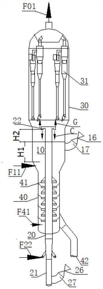
[0036] like figure 1 As shown, the implementation process is as follows:

[0037] The first reactor 10 is a turbulent fluidized bed reactor, the feedstock oil F11 enters from below the fluidized bed of the first reactor 10, and the regenerated catalyst enters the fluidized bed from the regenerated catalyst inlet pipe 17;

[0038] The second reactor 20 is a riser. The riser is in the middle of the first reactor 10 and the stripping section 40. Light hydrocarbons with a real boiling point lower than 360°C enter the second reactor 20 from the bottom as the second reaction raw material F22 to regenerate the catalyst. Enter from the regenerated catalyst inlet pipe A 27;

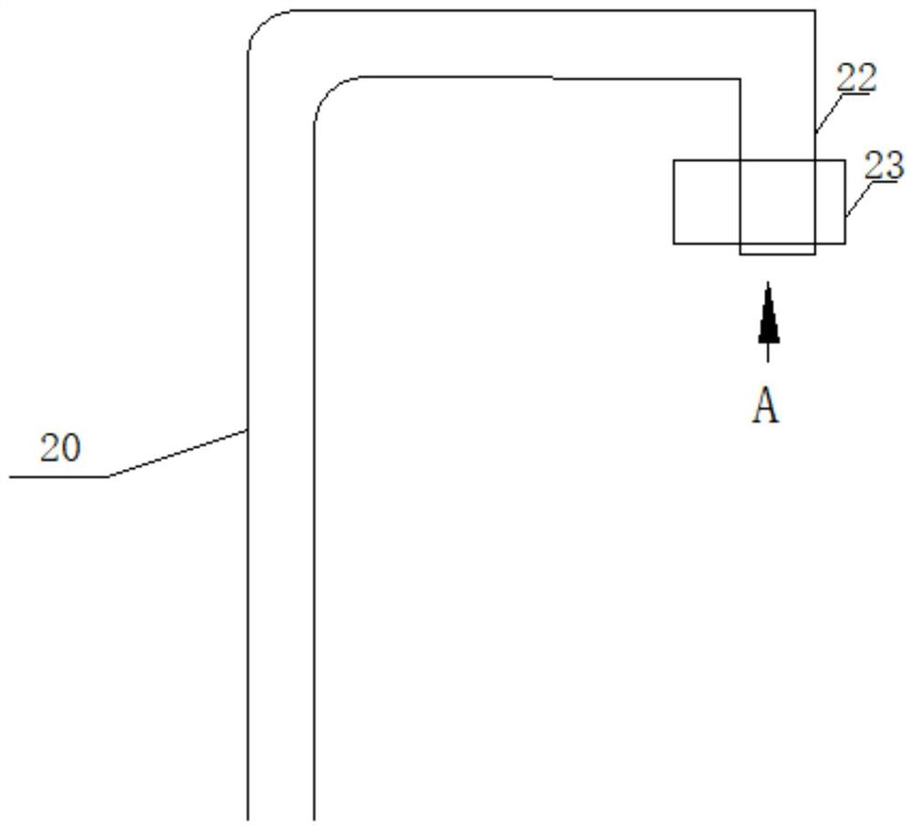
[0039] The outlet 22 of the second reactor 20 is turned downward, and the outlet 22 is above the catalyst in the fluidized bed of the first reactor 10. The reacted stream flows out of the second reactor 20 downward through the outlet 22, and the catalyst C gravity settles to the bottom. In the fluidized bed of t...

Embodiment 1

[0041] The first reactor 10 is a fluidized bed reactor, the regenerant enters the fluidized bed reactor, the reacted catalyst settles from the fluidized bed reactor 10 to the stripping section 40, the second reactor 20 is in the form of a riser, and the first reactor 20 is in the form of a riser. The second reactor 20 is arranged in the center of the first reactor 10 and the stripping section 40, and the superficial gas velocity (gas volume flow divided by the cross-sectional area) in the first reactor 10 is not greater than 1.5 m / s, preferably not greater than 1.0 m / s, the catalyst material level H1 in the fluidized bed is calculated according to the average density of the catalyst, the second reactor outlet 22 and the catalyst material level H2 in the first reactor 10 are designed to be 1.0-3.0 meters, and the second reactor outlet 22 is one or more; catalyst circulation and catalyst stripping are well known and will not be repeated here.

Embodiment approach 2

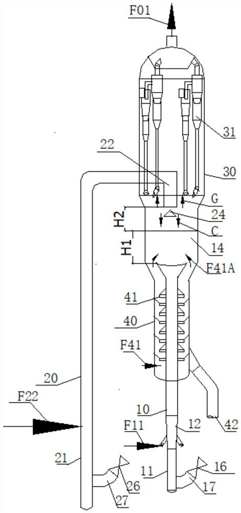
[0043] like figure 2 As shown, the implementation process is as follows:

[0044] The first reactor 10 is in the form of a common riser plus a fluidized bed, the fluidized bed reaction zone 14 is above, and the heavy feedstock oil F11 first enters the first reactor 10 in the riser section, and in the conical reaction section whose diameter gradually expands That is, the reaction is carried out in the gradually expanding reaction zone 12, and the raw material oil is converted into intermediate components mainly composed of gasoline and diesel oil, and then enters the fluidized bed reaction zone 14 upward, and the catalyst density is 200kg / m2. 3 Under the condition of the fluidized bed, the intermediate components are continuously cracked and converted into liquefied gas and dry gas components. The catalyst storage in the fluidized bed reaction zone 14 is based on the reaction catalyst weight hourly space velocity of 4-6 (1 / h) in this zone. It is determined that the fluidized ...


PUM


Abstract

The invention belongs to the technical field of gas-solid fluidized bed reaction conversion, and particularly relates to a catalyst distribution method for gas-solid fluidized reaction catalyst coupling utilization, after a reaction in a second reactor, the catalyst is dispersed and settled to a fluidized bed of a first reactor from above, and continues to participate in the reaction in the fluidized bed; the product gas of the second reactor directly flows out and does not enter the fluidized bed, so that catalyst coupling utilization of different reactors is realized, the product gas does not influence each other, and the utilization effect and reaction efficiency of the catalyst are improved.

Description

technical field [0001] The invention belongs to the technical field of gas-solid fluidized bed reaction conversion, and in particular relates to a catalyst distribution method for coupled utilization of gas-solid fluidized reaction catalysts, which realizes efficient coupled utilization of catalysts in the catalytic conversion process of hydrocarbon reaction raw materials. Dispensing device corresponding to the above method. Background technique [0002] The gas-solid circulation fluidization reaction is a typical chemical reaction process. The thermal process is significant or the catalyst performance changes significantly. The reaction process from the catalyst to the regeneration should be tried continuously. device. [0003] Since multiple raw materials are often required to react at the same time, and the properties of different raw materials are very different, the influence of the reaction process on the catalyst is very different, and the requirements for the perfor...

Claims


Application Information

Patent Timeline
Patent Type & Authority Applications(China)
IPC IPC(8): B01J8/24B01J8/00
CPCB01J8/24B01J8/008B01J8/001B01J8/0015B01J8/005B01J2208/00752B01J2208/00761
Inventor 李荻郭江伟石宝珍
Owner QINGDAO JINGRUN PETROCHEM DESIGN INST CO LTD
Why Eureka
Try Eureka