Efficient in-situ fuel gas thermal desorption heating device and method

A technology of additional heat and gas, applied in the field of high-efficiency in-situ gas heat desorption and additional heat devices, can solve the problems of increased heat loss of combustion exhaust, increased gas consumption, and low energy utilization rate, so as to realize heat energy and improve progress The effect of reducing gas temperature and reducing gas consumption

Pending Publication Date: 2022-06-24
JIANGSU DDBS ENVIRONMENT REMEDIATION
View PDF0 Cites 1 Cited by
  • Summary
  • Abstract
  • Description
  • Claims
  • Application Information

AI Technical Summary

Problems solved by technology

[0004] Due to the large amount of air induced during the combustion process of the traditional heating type, the combustion temperature decreases and the heat loss of the combustion exhaust increases; in addition, the exposed part of the heating well on the ground is long, and the high-temperature exhaust gas is discharged to heat the formation in a single round-trip, resulting in The heat is not fully used for the effective heating of the underground contaminated soil bottom layer, resulting in a low energy utilization rate of in-situ gas thermal desorption (30-60%), increased gas consumption, and increased repair costs

Method used


Image

  • Efficient in-situ fuel gas thermal desorption heating device and method
  • Efficient in-situ fuel gas thermal desorption heating device and method

Examples


Embodiment example 1

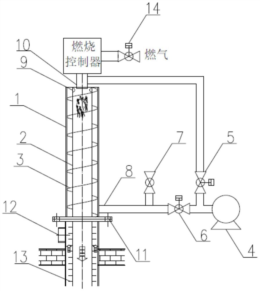
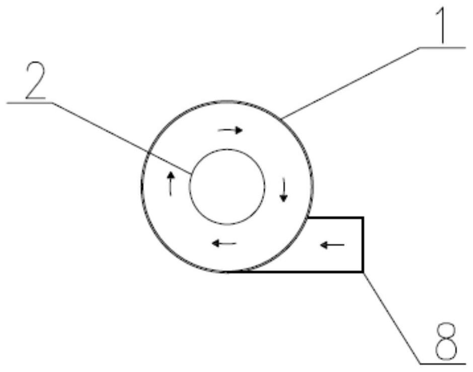
[0034] refer to figure 1 , figure 2 , This embodiment case 1 discloses a high-efficiency in-situ gas thermal desorption additional heat device, including a combustion controller, a combustion well, a blower 4, and a heating well 11. The combustion controller is arranged on the upper part of the combustion well, and the combustion controller is provided with a gas interface and a gas regulating valve 14; the lower part is connected with a gas / primary air mixing pipe 10, and the lower part of the mixing pipe is provided with a plurality of distribution holes, and extends into the upper part of the inner pipe of the combustion well; The combustion well is a cylinder composed of inner and outer tubes arranged concentrically. A spiral diversion groove 3 is arranged between the inner tube 2 and the outer tube 1 of the combustion well, and a plurality of secondary inlets are arranged on the inner tube wall on the upper part of the spiral diversion groove at the top. The air distrib...

Embodiment example 2

[0039] refer to figure 1 , figure 2 , the structure principle of this implementation case is basically the same as that of implementation case 1, the difference is: in this implementation case, the in-situ gas thermal desorption additional heat device is used as a waste gas reburning well for the purification treatment of waste gas. Close the secondary air regulating valve 6, open the primary air regulating valve 5, and turn on the blower. The extraction tail gas from the heat removal additional heat site is first subjected to condensation and separation treatment, and then screwed into the cavity between the inner and outer tubes of the combustion well through the waste gas interface valve 7, and exchanges heat with the high-temperature waste gas generated by the combustion in countercurrent. It reaches 200~300℃, and enters the combustion chamber through the secondary air intake distribution hole. The high-temperature exhaust gas and the high-speed spiral make the exhaust g...


PUM


Abstract

The invention discloses an efficient in-situ fuel gas thermal desorption heating device which comprises a combustion controller, a combustion well, an air blower and a heating well. The combustion well is a concentric barrel composed of an inner pipe and an outer pipe, a spiral flow guide groove is formed between the inner pipe and the outer pipe, a plurality of air inlet distribution holes are formed in the inner pipe wall on the upper portion of the top spiral flow guide groove, and the outer pipe of the combustion well is connected with a secondary air spiral air inlet of an air blower. The air blower supplies primary air and secondary air to the combustion well in a grading mode and is interlocked with gas supply, and meanwhile a waste gas connector valve is arranged on a secondary air inlet pipeline. Fins are arranged on the outer wall of the heating well inner pipe in a partitioned mode according to the stratum pollution condition. Secondary air / condensed waste gas is tangentially fed and spirally exchanges heat with combustion high-temperature flue gas, so that the gas inlet temperature is increased, combustion components are fully mixed, efficient combustion of fuel gas is realized, and the comprehensive consumption of the fuel gas is reduced; meanwhile, fins are arranged on the outer wall of the heating well inner pipe in a partitioned mode, the pertinence of heating the underground polluted stratum through heat energy is improved, and comprehensive and efficient utilization of the heat energy is achieved.

Description

technical field [0001] The invention relates to the field of polluted site remediation, in particular to a high-efficiency in-situ gas-fired thermal desorption additional heat device and method. Background technique [0002] In-situ gas thermal desorption is to burn natural gas, liquefied natural gas and other fuels as a heat source, input thermal energy into the ground, and heat the target treatment area through heat conduction, so that the soil temperature rises, the pollutants in the soil migrate into the gas phase, and then the soil gas phase is extracted. Or multi-phase extraction is sent to the exhaust gas treatment system to achieve the process of removing target pollutants. Because it is suitable for strata with low permeability and poor homogeneity, it is not limited by soil moisture content, and the soil can be heated to above 100 °C, and the restoration period is short. The in-situ gas thermal desorption technology has unique advantages in site restoration. , has...

Claims


Application Information

Patent Timeline
Patent Type & Authority Applications(China)
IPC IPC(8): F23D14/60F23D14/22F23D14/62F24H3/04B09C1/06
CPCF23D14/60F23D14/22F23D14/62F24H3/0488B09C1/06
Inventor 葛传芹刘志阳沈诣张乙臧常娟
Owner JIANGSU DDBS ENVIRONMENT REMEDIATION
Why Eureka
Try Eureka