Welding rod boxing machine
A cartoning machine and welding rod technology, applied in packaging, transportation packaging, packaging protection, etc., can solve the problems of discontinuity and low boxing efficiency, so as to improve practicability, improve boxing efficiency, and save grabbing time and space Effect
- Summary
- Abstract
- Description
- Claims
- Application Information
AI Technical Summary
Problems solved by technology
Method used
Image

Examples
Embodiment 1
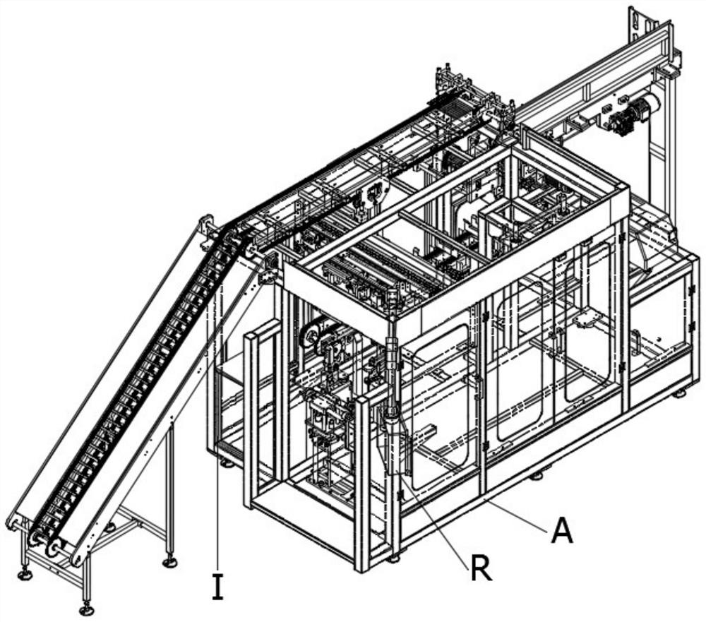
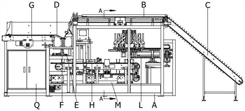
[0049] like Figure 1-4 The shown welding rod cartoning machine includes a frame A, the upper end of the frame A is installed with a feeding storage mechanism B, and one end of the frame A is installed with a feeding climbing mechanism C connected with the feeding storage mechanism B, The feeding and storage mechanism B is provided with a feeding mechanism D at one end away from the feeding and climbing mechanism C. The bottom of the feeding mechanism D is provided with a feeding mechanism F, and a feeding mechanism F is installed below the feeding feeding mechanism F. Material shaping and conveying mechanism H, a chain conveying and forming mechanism M is installed below the blanking conveying mechanism H, a cardboard suction mechanism L is installed above the chain conveying and forming mechanism M, and an accumulation conveyor chain is installed on the side of the unloading mechanism D. G, a hydraulic buffer E is installed on the side of the blanking mechanism F, a blanking...
Embodiment 2
[0054] This embodiment is further optimized on the basis of Embodiment 1. The blanking mechanism 40 includes a bottom plate 4001. Please refer to Figure 20-23 , a fixing plate 4004 is installed above the bottom plate 4001, a lifting cylinder 4024 is fixedly installed at the bottom of the bottom plate 4001, and the output end of the lifting cylinder 4024 penetrates the bottom plate 4001 and is fixedly connected with the bottom of the fixing plate 4004. The upper surface of 4004 is fixedly installed to cooperate with the first adjustment plate 4005 and the second adjustment plate 4006. The outer sides of the first adjustment plate 4005 and the second adjustment plate 4006 are installed with a first flip plate 4007 that is rotatably connected to them. A second turning plate 4014 is fixedly installed on the outside of the turning plate 4007, and a fixing seat 4016 is installed under the bottom plate 4001 to be slidably connected with it. , one end of the turning mechanism is rota...
Embodiment 3
[0057] This embodiment is further optimized on the basis of Embodiment 2. The two-end shaping mechanism 42 includes an end shaping bottom plate 18. Please refer to Figure 24-26, a cylinder bracket 4222 is fixedly installed on the end shaping bottom plate 18, a second cylinder fixing plate 4221 is fixedly installed on the cylinder bracket 4222, and a cylinder 4219 is fixedly installed on the second cylinder fixing plate 4221, and the cylinder The output end of 4219 penetrates the cylinder bracket 4222 and is fixedly connected with the push plate 4203. The outside of the push plate 4203 is installed with a spring steel sheet 4205 that matches it. The position mechanism is connected with the spring steel sheet 4205, that is, when the chain is positioned to the 42 position of the shaping mechanism at both ends, the cylinder 4219 starts to act. When the side page is opened and pushed to a certain extent, the spring steel sheet 4205 is blocked by the limiting mechanism, the spring ...
PUM
 Abstract
Description
Claims
Application Information
 - R&D Engineer
- R&D Manager
- IP Professional
- Industry Leading Data Capabilities
- Powerful AI technology
- Patent DNA Extraction
Browse by: Latest US Patents, China's latest patents, Technical Efficacy Thesaurus, Application Domain, Technology Topic.
© 2024 PatSnap. All rights reserved.Legal|Privacy policy|Modern Slavery Act Transparency Statement|Sitemap