Cooling structure for chassis of reduction furnace

A chassis cooling and reduction furnace technology, applied in inorganic chemistry, silicon compounds, chemical instruments and methods, etc., can solve the problems of low deposition reaction rate, reduced polysilicon conversion rate, high inlet gas velocity, etc.

Pending Publication Date: 2022-06-28
XINJIANG DAQO NEW ENERGY +1
View PDF0 Cites 0 Cited by
  • Summary
  • Abstract
  • Description
  • Claims
  • Application Information

AI Technical Summary

Problems solved by technology

[0003] The inlet nozzle and the tail gas outlet of the existing reduction furnace are all located on the furnace pan of the reduction furnace, which leads to the following disadvantages: first, it is easy to cause part of the feed mixture gas to take a short circuit and be directly discharged from the tail gas outlet with low pressure, which reduces the polysilicon. Conversion rate
Second, due to the high speed and low temperature of the feed gas at the gas inlet, a concentration gradient and a temperature gradient must be generated in the vertical direction of the reduction furnace, resulting in a low deposition reaction rate of polysilicon at the root of the electrode, an

Method used


Image

  • Cooling structure for chassis of reduction furnace
  • Cooling structure for chassis of reduction furnace
  • Cooling structure for chassis of reduction furnace

Examples


Embodiment Construction

[0023] The present invention will be further described in detail below in conjunction with the accompanying drawings and embodiments.

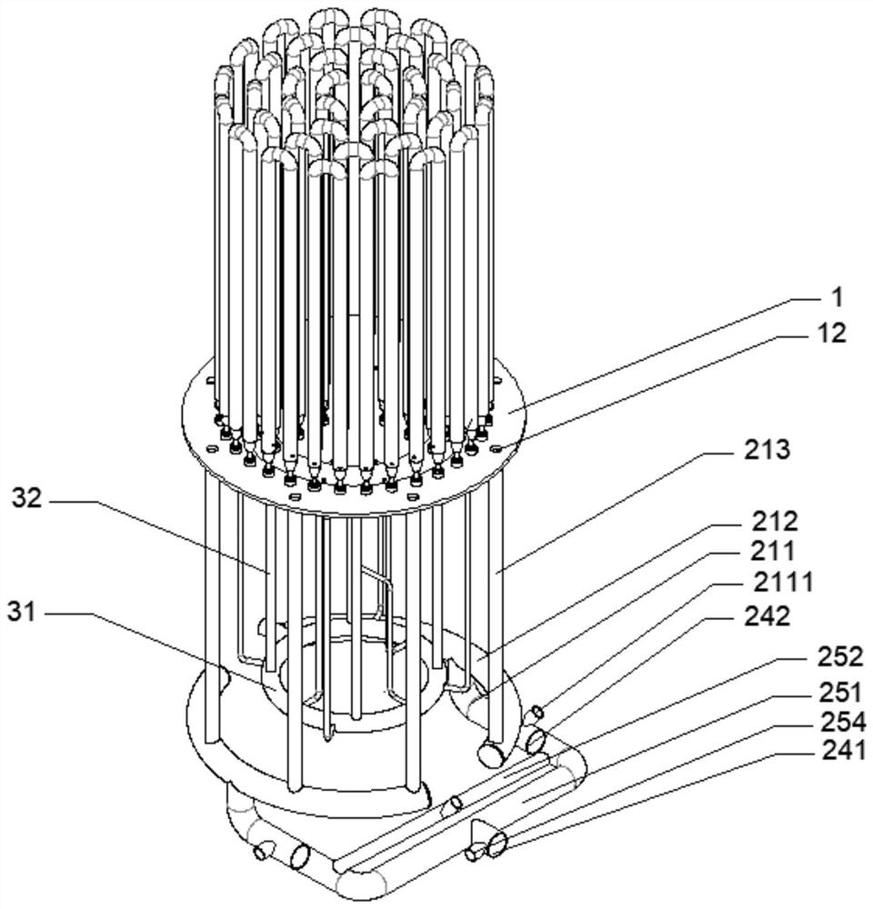
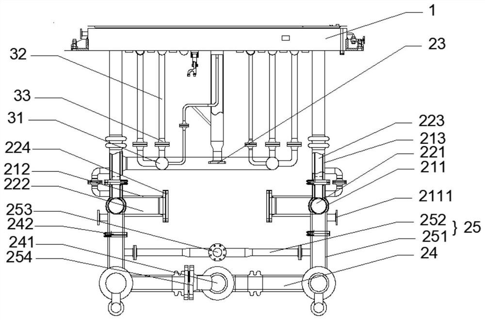
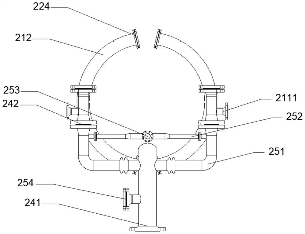
[0024] like Figure 1 to Figure 3 As shown, an embodiment of the present invention provides a reduction furnace chassis cooling structure, the structure comprising:

[0025] Chassis 1, the chassis 1 has cooling pipes and a plurality of exhaust holes 12;

[0026] Cooling part, the cooling part includes chassis casing and exhaust casing, the chassis casing includes water inlet pipe, exhaust pipe and drainage pipe 23, the water inlet pipe is sleeved outside the exhaust pipe, the water inlet pipe is connected to the cooling pipe, the cooling pipe Connected to the drainage pipe 23, one end of the exhaust pipe is connected to the plurality of exhaust holes 12, the exhaust sleeve includes a first gas pipe 24 and a first water pipe 25, the first gas pipe 24 is communicated with the other end of the exhaust pipe, and the first water pipe 25 is sleeve...


PUM


Abstract

The invention discloses a reduction furnace chassis cooling structure, relates to the technical field of polycrystalline silicon production equipment, and mainly aims to provide a reduction furnace chassis cooling structure capable of uniformly discharging tail gas, ensuring more uniform distribution of a temperature field and a velocity field in a reduction furnace and enabling growth rates of silicon rods at different positions to tend to be balanced. According to the main technical scheme, the chassis cooling structure of the reduction furnace comprises a chassis, and the chassis is provided with a cooling pipeline and a plurality of exhaust holes; the chassis sleeve comprises a water inlet pipeline, a tail gas pipeline and a drainage pipeline, the tail gas pipeline is sleeved with the water inlet pipeline, the water inlet pipeline is connected to the cooling pipeline, the cooling pipeline is connected to the drainage pipeline, and one end of the tail gas pipeline is connected to the multiple exhaust holes; the first gas pipe communicates with the other end of the tail gas pipeline, and the first water pipe sleeves the first gas pipe. The device is mainly used for discharging and cooling the tail gas of the reduction furnace.

Description

technical field [0001] The invention relates to the technical field of polysilicon production equipment, in particular to a bottom cooling structure of a reduction furnace. Background technique [0002] At present, polysilicon production enterprises mainly use the modified Siemens method to manufacture polysilicon. The production process of this method is to synthesize trichlorosilane with hydrogen chloride and silicon powder at a certain temperature, and then purify the trichlorosilane fine filling, and the purified high-purity trichlorosilane After the chlorohydrogen silicon and hydrogen are mixed in proportion, they are passed into the polysilicon reduction furnace at a certain temperature and pressure, and the vapor deposition reaction is carried out on the electrified high temperature silicon core to generate polysilicon, and the unreacted exhaust gas is discharged from the exhaust gas outlet on the furnace plate. , enter the next process, when manufacturing polysilicon...

Claims


Application Information

Patent Timeline
IPC IPC(8): C01B33/035
CPCC01B33/035
Inventor 莫可璋谭忠芳杨涛丁建
Owner XINJIANG DAQO NEW ENERGY
Why Eureka
Try Eureka