
Industrial wastewater treatment device

A treatment device and technology for industrial wastewater, applied in the fields of energy wastewater treatment, water/sewage multi-stage treatment, water/sludge/sewage treatment, etc., can solve the problems of insufficient safety, reduced wastewater treatment efficiency, and long waiting time for treatment, etc. Achieve the effect of improving processing efficiency, saving waiting time, and reducing contact

Inactive Publication Date: 2022-07-08
周天桥
View PDF2 Cites 0 Cited by
  • Summary
  • Abstract
  • Description
  • Claims
  • Application Information

AI Technical Summary

Problems solved by technology

At present, the existing industrial wastewater treatment device contains a large amount of particulate impurities in the sewage and cannot be filtered in place at one time. The existing publication number CN201922158226.5 is an industrial wastewater treatment device; The motor, motor shaft, stirring fan blade, activated carbon net, activated carbon, treatment tank, and drug inlet are co-ordinated to allow the powder and debris inside the industrial wastewater to settle at the bottom of the sedimentation tank through long-term precipitation; Long-term precipitation is required, so that the device cannot continue to treat wastewater, and it takes a certain interval of time to perform the next filtration, and the waiting time for treatment is long; Another example is CN202020411188.X, an industrial wastewater treatment device that separates solids from liquids through mesh bags , it is necessary for the staff to take out the mesh bag regularly and replace it, and stop the discharge of waste water during the replacement, which makes the waiting time for waste water treatment, reduces the efficiency of waste water treatment, and increases the contact between staff and waste water, which is not safe enough

Method used


Image

  • Industrial wastewater treatment device
  • Industrial wastewater treatment device
  • Industrial wastewater treatment device

Examples


Embodiment Construction

[0031] In order to make the objectives, technical solutions and advantages of the present invention clearer, the present invention will be further described in detail below with reference to the specific embodiments and the accompanying drawings. It should be understood that these descriptions are exemplary only and are not intended to limit the scope of the invention. Also, in the following description, descriptions of well-known structures and techniques are omitted to avoid unnecessarily obscuring the concepts of the present invention.

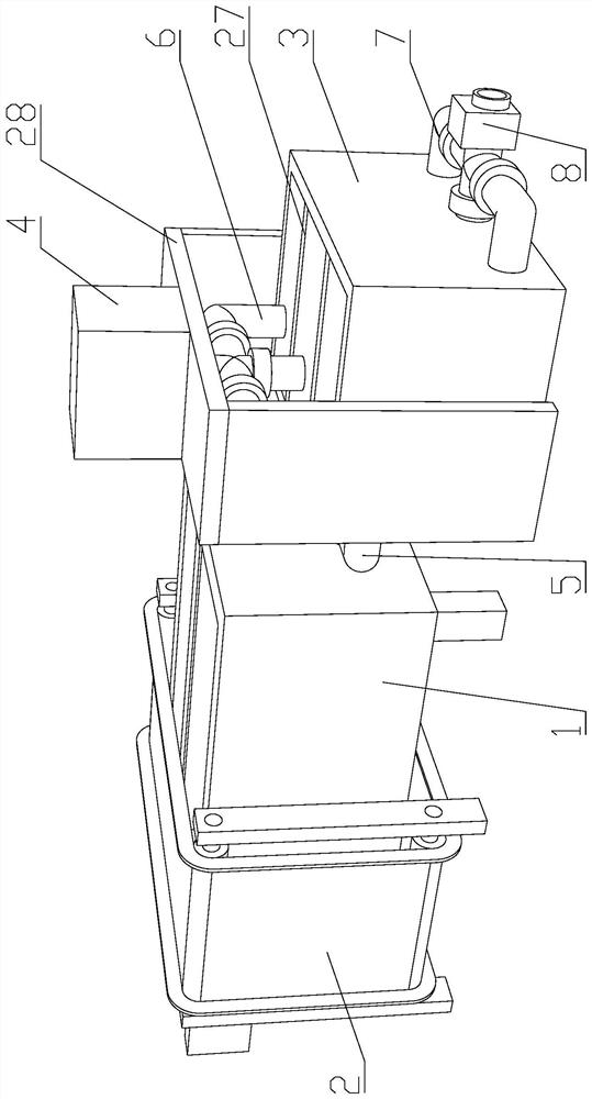
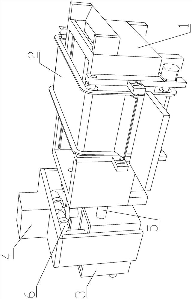
[0032] like Figure 1-5 As shown, an industrial wastewater treatment device proposed by the present invention includes a primary treatment tank 1, a filtering device 2, a secondary treatment tank 3, a flocculant tank 4, a first connecting pipe 5, a second connecting pipe 6, a third connecting pipe 7, suction pump 8 and second support frame 28;

[0033] The sewage enters the primary treatment tank 1 through the filtering equipment 2, and t...


PUM


Abstract

The industrial wastewater treatment device comprises a primary treatment box, filtering equipment, a secondary treatment box and a flocculating agent box, the flocculant box is arranged right above the secondary treatment box, the liquid inlet end of the second connecting pipe is communicated with the flocculant box, and the liquid outlet end of the second connecting pipe faces the secondary treatment box; the third connecting pipe is arranged on the secondary treatment box and is communicated with the biological treatment box; the multiple sets of rotating rollers are rotationally arranged on the first supporting frame and are in transmission connection through the conveying belt. The motor is arranged on the first supporting frame and connected with the rotating roller. A scraping assembly is arranged on the first supporting frame; the filter screen is slidably arranged on the treatment box main body and is connected with a telescopic rod of the first cylinder; the push plate is in sliding connection with the treatment box main body through a guide sliding block; and the second cylinder is arranged on the treatment box main body and is connected with the push plate. The device automatically removes solids in wastewater, reduces manual contact with wastewater, is safer and more convenient, realizes continuous treatment of wastewater, saves waiting time during treatment, and improves wastewater treatment efficiency.

Description

technical field [0001] The present invention relates to the technical field of wastewater treatment equipment, in particular to an industrial wastewater treatment device. Background technique [0002] Industrial wastewater includes production wastewater, production sewage and cooling water, and refers to the wastewater and waste liquid produced in the industrial production process, which contain industrial production materials, intermediate products, by-products and pollutants generated in the production process lost with water. There are various types of wastewater with complex components, such as electrolytic salt industrial wastewater containing mercury, heavy metal smelting industrial wastewater containing various metals such as lead and cadmium, electroplating industrial wastewater containing various heavy metals such as cyanide and chromium, and petroleum refining industrial wastewater containing Phenol, pesticide manufacturing industrial wastewater contains various pe...

Claims


Application Information

Patent Timeline
Patent Type & Authority Applications(China)
IPC IPC(8): C02F9/14
CPCC02F9/00C02F1/001C02F2001/007C02F1/5281C02F3/00C02F2303/16Y02W10/10
Inventor 周天桥董新良吴慧东
Owner 周天桥
Learn More