Laser metal deposition preparation method for boss structure of engine diffuser

A diffuser and engine technology, applied in the direction of additive manufacturing, process efficiency improvement, additive processing, etc., can solve problems such as long engine maintenance cycle, high-energy beam laser heating, and parts collapse, so as to reduce the amount of machining and improve Efficiency, impact reduction effect

Pending Publication Date: 2022-07-12
航发优材(镇江)增材制造有限公司
View PDF17 Cites 1 Cited by
  • Summary
  • Abstract
  • Description
  • Claims
  • Application Information

AI Technical Summary

Problems solved by technology

[0004] The purpose of the present invention is to solve the problems such as collapse, oxidation, deformation and even cracking of parts due to the long-term intense heating of high-energy beam laser during the laser direct metal deposition repair process of thin-walled curved surface parts, and the heat accumulation effect in the repair area. The platform us

Method used


Image

  • Laser metal deposition preparation method for boss structure of engine diffuser
  • Laser metal deposition preparation method for boss structure of engine diffuser
  • Laser metal deposition preparation method for boss structure of engine diffuser

Examples


specific Embodiment approach 1

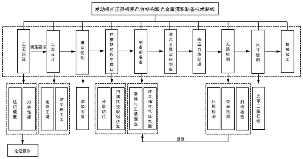
[0042] A direct laser preparation method for an engine diffuser casing boss structure, comprising the following steps:

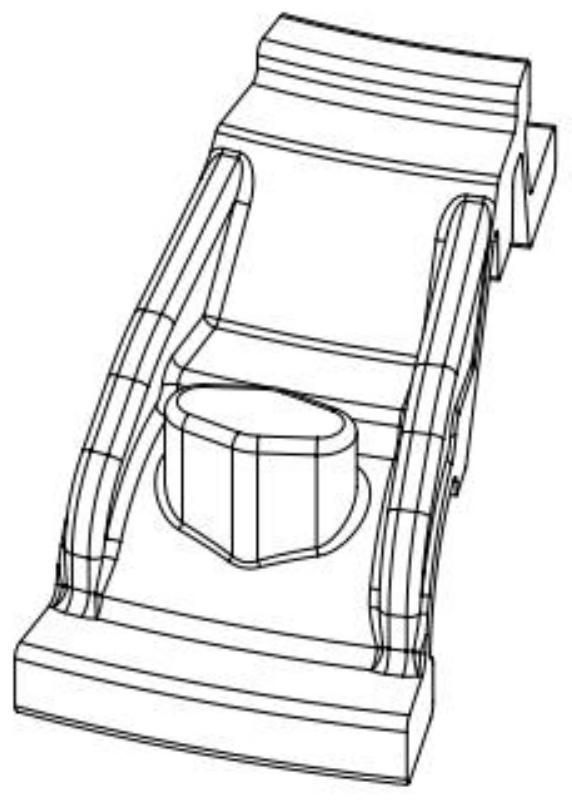
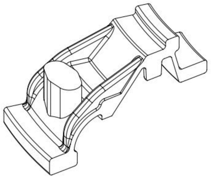
[0043] 1. The engine diffuser case boss is missing.

[0044] The material is: ZTA15, the size of the missing boss is about 40mm×25mm×30mm, the shape is elliptical, and the base surface of the area to be prepared is an arc surface.

[0045] 2. The preparation process is implemented.

[0046] (1) Through the process optimization in the early stage, the microstructure hardness and mechanical properties under the optimal process parameters for the preparation of the diffuser casing boss are obtained, and the index requirements are met, and a process demonstration report is output;

[0047] (2) According to the structural characteristics of the engine diffuser casing, the positioning tooling is designed to ensure that the offline simulation and scanning path planning accuracy reach 0.1mm. At the same time, the anti-deformation conformal tooling 15 is designed an...

specific Embodiment approach 2

[0070] A direct laser preparation method for an engine diffuser casing boss structure, comprising the following steps:

[0071] 1. The engine diffuser case boss is missing.

[0072] The material is: ZTA15, the height of the boss is out of tolerance by about 10mm, and the base surface of the area to be prepared is flat.

[0073] 2. The preparation process is implemented.

[0074] (1) According to the previous process demonstration report, the optimal process parameters were used to prepare the engine diffuser case boss by laser metal deposition.

[0075] (2) According to the structural characteristics of the engine diffuser casing, the positioning tooling is designed to ensure that the offline simulation and scanning path planning accuracy reach 0.1mm. At the same time, the anti-deformation conformal tooling is designed and manufactured, which has the functions of water cooling and air cooling, and controls the preparation to be prepared. The deformation of the part itself in...


PUM

PropertyMeasurementUnit
Diameteraaaaaaaaaa

Abstract

The invention discloses a laser metal deposition preparation method for a boss structure of an engine diffuser casing, which comprises the following steps of: outputting a process argument report through early-stage process verification; designing a positioning tool, and designing and manufacturing an anti-deformation follow-up tool; adding allowance to the size of the boss, and simulating the scanning path and reliability of the boss by software to obtain a scanning path program; before preparation, the parts, the shape follow-up tool and the positioning tool need to be assembled and installed, and the atmosphere of inert gas in the preparation process is created by adopting a flexible high-temperature-resistant film; carrying out boss laser metal deposition preparation according to the verified program, and after the temperature of the boss and the surface of the part is reduced, stopping filling the inert gas; putting the tool and the part into a vacuum heat treatment furnace; detecting the prepared boss, and if not, repairing the prepared boss; performing size comparison on the optical three-dimensional scanning model before and after the boss is prepared, wherein a result is a deviation measured value; and the prepared boss is machined. The invention provides a complete set of mature laser metal deposition preparation method for a boss structure of a case of an engine diffuser.

Description

technical field [0001] The invention relates to the technical field of laser additive manufacturing, in particular to a laser direct deposition preparation method of an engine diffuser boss structure. Background technique [0002] Laser metal deposition (LMD) is a laser additive manufacturing process for metal materials, and it is also an excellent manufacturing technology for processing titanium and its alloys. LMD belongs to the manufacturing process of directional energy deposition by adding metal materials (metal powder, metal wire, metal strip). In this process, the high-energy laser beam is directly injected into the surface of the workpiece to form a molten pool. Directionally transported to the molten pool, "stacked" layer by layer, and finally "printed" out of the metal part. Not only can the technology be used to repair parts that are worn out or considered scrap in the past, it also enables the manufacture of "3D" parts with complex geometric features or lightwei...

Claims


Application Information

Patent Timeline
IPC IPC(8): B22F10/22B22F10/366B22F10/85B33Y10/00B33Y50/02
CPCB22F10/22B22F10/366B22F10/85B33Y10/00B33Y50/02Y02P10/25
Inventor 张峰庞义斌叶紫阳张强孙兵兵赵海生
Owner 航发优材(镇江)增材制造有限公司
Why Eureka
Try Eureka