
Static rotational flow well washing device and method for washing in-situ leaching drill hole

A static and in-situ immersion technology, used in earth-moving drilling, wellbore/well components, and process efficiency improvement. It can solve problems such as low mud and sand washing efficiency, achieve a clear design concept, improve fluid dynamic pressure, and increase self-weight. Effect

Pending Publication Date: 2022-07-12
BEIJING RESEARCH INSTITUTE OF CHEMICAL ENGINEERING AND METALLURGY
View PDF0 Cites 0 Cited by
  • Summary
  • Abstract
  • Description
  • Claims
  • Application Information

AI Technical Summary

Problems solved by technology

Although the impact force on the blockage in the normal direction is great, the cleaning efficiency of the scaled chemical precipitation on the inner wall of the filter (the wall between the filter holes) and the mud and sand deposited in the sand settling pipe is relatively low

Method used


Image

  • Static rotational flow well washing device and method for washing in-situ leaching drill hole
  • Static rotational flow well washing device and method for washing in-situ leaching drill hole
  • Static rotational flow well washing device and method for washing in-situ leaching drill hole

Examples


Embodiment 1

[0055] Uranium leaching well in a certain area of ​​Erlian Basin, Inner Mongolia

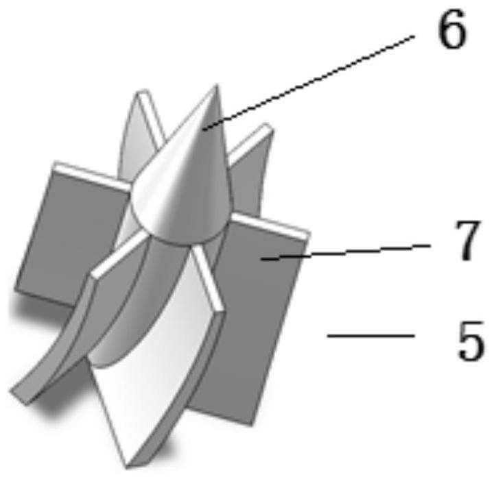
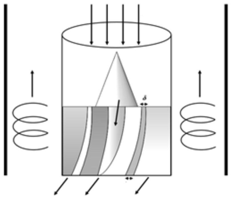
[0056] The depth of the uranium mine is more than 300m, the inner diameter of the pumping hole casing is DN 128mm; the design pressure of the fan is 5Mpa, the actual work is about 3.5MPa, the inner diameter of the air conveying pipe is DN 25mm, and the length of the steel pipe is 1m; The diameter of the circle is 9mm; the number of swirl blades is 6, that is, the rotation angle of the blade is 60° (360° / 6=60°), the helix angle is set to 60°, the vertical height is 25mm, and the width is 7mm. The diameter of the cylinder is 9mm, which is convenient for the welding of the blade and the inner wall of the gas delivery pipe, the thickness of the top of the blade is 1mm, and the thickness of the bottom is 2mm, such as image 3 shown.

[0057] According to the results of measuring the height of the sand in the sand tube, two wells with similar heights of sand are selected, with a height of about 6m. ...

Embodiment 2

[0059] A uranium leaching well in a certain place in the Yili Basin, Xinjiang, is an in-situ leaching uranium well that has been in operation for many years. During normal production, the pumping volume is generally greater than 4m 3 / h, when the pumping volume drops to 2m 3 When the / h is below, it is considered that the downhole blockage is serious, and the purpose of well flushing is to increase the pumping volume.

[0060] The depth of the uranium mine is more than 350m, the inner diameter of the pumping hole casing is DN 128mm; the design pressure of the fan is 5MPa, the actual working is about 3.5MPa, the inner diameter of the air conveying pipe is DN 25mm, and the length of the steel pipe is 1m; The diameter of the circle is 9mm; the number of swirl blades is 8, that is, the blade rotation angle is 45° (360° / 8=45°), the helix angle is set to 50°, the vertical height is 25mm, and the width is 7mm. The diameter of the cylinder is 9mm, which is convenient for the welding...


PUM


Abstract

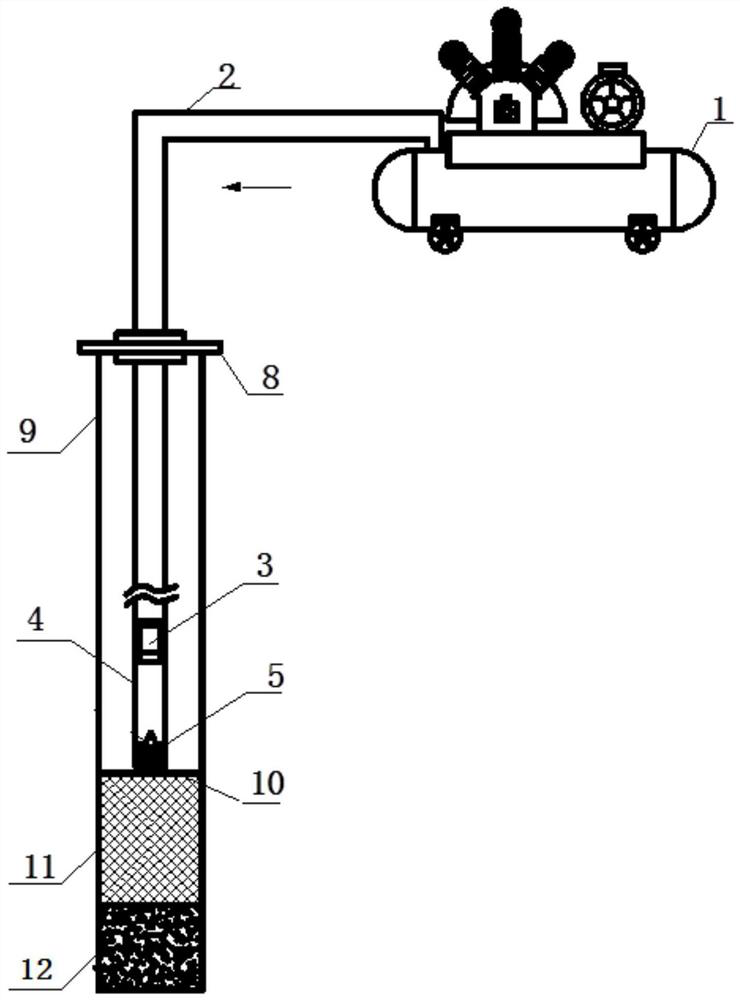
The invention relates to the technical field of in-situ leaching uranium mining, in particular to a static rotational flow well washing device and method for cleaning in-situ leaching drill holes. According to the device, an air compressor is connected with an air conveying hose, and the air conveying hose is connected with a steel pipe through an adapter substitute; a rotational flow piece is arranged at the tail end in the steel pipe and comprises a flow guide cone and a cylinder welded to the bottom face of the flow guide cone, the flow guide cone is a cone, and rotational flow blades are welded to the side face of the cylinder at intervals; the thickness of each swirl vane is gradually expanded from top to bottom; the top end of the flow guide cone faces the conversion connector end. The method comprises the following steps: putting a steel pipe into a filter or a sand setting pipe at the bottom end of an in-well sleeve; an air compressor is started, gas enters the casing pipe in the well through the gas conveying hose and the steel pipe, and well washing is started; and the sand setting height of the sand setting pipe in the well or the drilling hole flow is measured and recorded, the air compressor is closed after the well washing requirement is met, the gas conveying pipe is lifted out of a well opening, and well washing is finished. The device is high in well washing efficiency, easy to operate and convenient to manufacture.

Description

technical field [0001] The invention relates to the technical field of in-situ leaching and uranium mining, in particular to a static cyclone well flushing device and method for cleaning in-situ leaching boreholes. Background technique [0002] In-situ leaching of uranium is a uranium mining and metallurgy process that selectively extracts and recovers uranium metal from sandstone uranium ore bodies with certain permeability under natural burial conditions by drilling with chemical solutions. In this process, the leaching agent needs to be injected into the ground, seepage along the ore bed, and leaching the uranium in the ore to form a leaching solution and be lifted out of the surface. After hydrometallurgical treatment, the metal uranium in the leaching solution is separated and recovered. During the mining process, under the action of the hydraulic gradient, the fine particles of mud and silt in the ore layer migrate to the direction of the pumping well, causing mechanic...

Claims


Application Information

Patent Timeline
Patent Type & Authority Applications(China)
IPC IPC(8): E21B21/16E21B47/00
CPCE21B21/16E21B47/006Y02P10/20
Inventor 王亚安张翀王晓东姚益轩廖文胜杜志明王亚奴李沁慈
Owner BEIJING RESEARCH INSTITUTE OF CHEMICAL ENGINEERING AND METALLURGY
Learn More