Differential detection type optical accelerometer based on F-P cavity with adjustable cavity length

An accelerometer, F-P technology, applied in the direction of measuring acceleration, velocity/acceleration/shock measurement, acceleration measurement using inertial force, etc., can solve the problem of accuracy, dynamic range and environmental desensitization that cannot meet high-precision inertial navigation and guidance at the same time System and other issues, to achieve high reliability and integration, small relative position error, and improve detection accuracy

Active Publication Date: 2022-07-15
ZHEJIANG UNIV
View PDF12 Cites 0 Cited by
  • Summary
  • Abstract
  • Description
  • Claims
  • Application Information

AI Technical Summary

Problems solved by technology

However, traditional MEMS accelerometers, such as capacitive, piezoresistive, piezoelectric, and resonant, cannot meet the needs of high-precision inertial navigation and guidance systems in terms of accuracy, dynamic range, and environmental desensitization.

Method used


Image

  • Differential detection type optical accelerometer based on F-P cavity with adjustable cavity length
  • Differential detection type optical accelerometer based on F-P cavity with adjustable cavity length
  • Differential detection type optical accelerometer based on F-P cavity with adjustable cavity length

Examples


Embodiment Construction

[0033] The present invention will be further described below with reference to the accompanying drawings and embodiments.

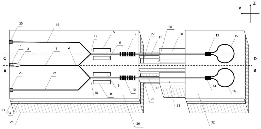
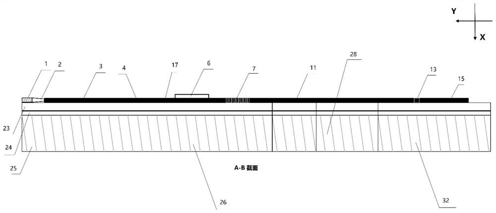
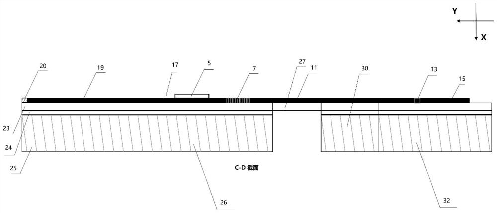
[0034] like Figure 1-4 As shown, the optical accelerometer of the present invention is symmetrically arranged about its central axis, including a broad-spectrum light source 1, a mode-spot converter 2, an input waveguide 3, a 1:2 Y-waveguide 4, a first upper electrode 5, and a first lower electrode 6. The first Bragg grating 7, the second lower electrode 8, the second upper electrode 9, the second Bragg grating 10, the first microbeam upper waveguide 11, the second microbeam upper waveguide 12, the first 1×2 type MMI coupling 13, the second 1×2 type MMI coupler 14, the first annular bending waveguide 15, the second annular bending waveguide 16, the first 2:1 type Y-waveguide 17, the second 2:1 type Y-waveguide 18, the first Output waveguide 19, first photodetector 20, second output waveguide 21, second photodetector 22, lithium niobate single crystal thin...


PUM

PropertyMeasurementUnit
reflectanceaaaaaaaaaa

Abstract

The invention discloses a differential detection type optical accelerometer based on an F-P (Fabry-Perot) cavity with adjustable cavity length. Light of a wide-spectrum light source enters the optical waveguide through coupling of the spot-size converter, and 50: 50 light splitting is achieved through the 1: 2 type Y waveguide. The upper branch and the lower branch of the Y waveguide are equal in length and are each composed of an electrode modulation area, a Bragg grating area and an MMI waveguide reflecting mirror. Wherein the Bragg grating area is located at the fixed end, the MMI waveguide reflector is located on the movable mass block, and the fixed end and the movable mass block are connected through a first micro beam-main beam-second micro beam three-beam structure. An F-P cavity is formed between the Bragg grating and the MMI coupler, and the optical waveguide on the micro beam serves as a part of the cavity length. The input acceleration can be obtained by performing differential calculation on light intensity information received by the upper photoelectric detector and the lower photoelectric detector. The system is high in detection precision, reliability and integration level, can eliminate common-mode noise interference, and has certain anti-electromagnetic interference capability.

Description

technical field [0001] The invention belongs to an optical accelerometer in the technical field of integrated optics and inertial sensing, and particularly relates to a differential detection type monolithic integrated optical accelerometer based on an F-P cavity with adjustable cavity length. Background technique [0002] Accelerometers based on MEMS technology have a wide range of applications and development prospects in consumer electronics, industrial automation, aerospace and other fields due to their low cost, small size, and light weight. However, traditional MEMS accelerometers, such as capacitive, piezoresistive, piezoelectric, resonant, etc., cannot simultaneously meet the requirements of high-precision inertial navigation and guidance systems in terms of accuracy, dynamic range, and environmental desensitization. The MOEMS accelerometer is inherently resistant to electromagnetic interference, and its potential for high detection accuracy makes it a popular resear...

Claims


Application Information

Patent Timeline
Patent Type & Authority Applications(China)
IPC IPC(8): G01P15/08G01P15/093G01C21/16B81B7/02G02F1/21G02F1/225
CPCG01P15/0802G01P15/093G01C21/165B81B7/02G02F1/213G02F1/225G01P2015/0862G01P2015/0877
Inventor 佘玄孙培基张奕群毕然陈侃舒晓武
Owner ZHEJIANG UNIV
Why Eureka
Try Eureka