Check patentability & draft patents in minutes with Patsnap Eureka AI!

Life detection method and system based on radar signal

A life detection and radar signal technology, applied in the field of life detection, can solve the problems of poor anti-interference ability and inaccurate extraction of heartbeat frequency, etc., and achieve the effect of strong anti-interference ability

Pending Publication Date: 2022-07-22
CHINA COAL RES INST
View PDF0 Cites 0 Cited by
  • Summary
  • Abstract
  • Description
  • Claims
  • Application Information

AI Technical Summary

Problems solved by technology

[0004] This application provides a life detection method and system based on radar signals to at least solve the technical problems of poor anti-interference ability and inability to accurately extract the heartbeat frequency in related technologies

Method used


Image

  • Life detection method and system based on radar signal
  • Life detection method and system based on radar signal
  • Life detection method and system based on radar signal

Examples


Embodiment 1

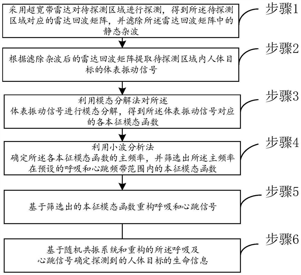
[0028] figure 1 A schematic flowchart of a radar signal-based life detection method provided according to an embodiment of the present application, such as figure 1 shown, can include:

[0029] Step 1: use an ultra-wideband radar to detect the area to be detected, obtain a radar echo matrix corresponding to the to-be-detected area, and filter out static clutter in the radar echo matrix;

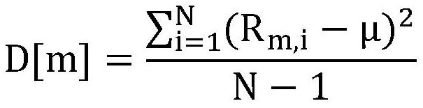
[0030] It should be noted that, assuming that the pulse signal transmitted by the UWB pulse radar is s(τ), the echo signal received by the antenna is: In the formula, n(τ, t) is the random noise signal of the receiver. Then, by discretizing the echo signal, we can obtain: where R(m,n) is the radar echo matrix, δ s and T s respectively represent the sampling interval of fast time and slow time, M and N represent the total number of sampling points of fast time and slow time, respectively, τ v (t) is the time delay of the human body micro-motion echo, t and τ are the slow time and fast ...

Embodiment 2

[0122] further, figure 2 A radar signal-based life detection system provided according to an embodiment of the present application, such as figure 2 As shown, the life detection system includes:

[0123] The first filtering module 100 is configured to detect the area to be detected by using an ultra-wideband radar, obtain a radar echo matrix corresponding to the area to be detected, and filter out static clutter in the radar echo matrix;

[0124] The extraction module 200 is used for extracting the body surface vibration signal of the human target in the area to be detected according to the radar echo matrix after filtering out the clutter;

[0125] A modal decomposition module 300, configured to perform modal decomposition on the body surface vibration signal by using a modal decomposition method to obtain each eigenmode function corresponding to the body surface vibration signal;

[0126] The screening module 400 is used for determining the main frequency of each eigenmo...


PUM


Abstract

The invention provides a life detection method and system based on a radar signal, and the method comprises the steps: carrying out the detection of a to-be-detected region through employing an ultra-wideband radar, obtaining a radar echo matrix, and filtering the static clutter in the radar echo matrix; according to the radar echo matrix after clutter filtering, extracting a body surface vibration signal of a human body target in the to-be-detected area; performing modal decomposition on the body surface vibration signal by using a modal decomposition method; determining the main frequency of each intrinsic mode function by using a wavelet analysis method, and screening out the intrinsic mode function of which the main frequency is within a preset breathing and heartbeat frequency band range; reconstructing breathing and heartbeat signals based on the screened intrinsic mode function; and determining the detected vital sign information of the human body target based on a stochastic resonance system and the reconstructed breathing and heartbeat signals. According to the technical scheme provided by the invention, the anti-interference capability is high, and the respiratory frequency and heartbeat frequency of the to-be-detected target can be accurately and quickly detected.

Description

technical field [0001] The present application relates to the technical field of life detection, and in particular, to a radar signal-based life detection method and system. Background technique [0002] Life detection radar is a high-tech life-saving equipment developed by integrating micro-power ultra-wideband radar technology and biomedical engineering technology. It is specialized in the search and positioning of survivors in emergency rescue missions such as earthquake disasters and landslides. It utilizes the characteristics of nanosecond electromagnetic wave pulse with wide spectrum, strong penetration, high resolution, good anti-interference, low power consumption, etc. It can penetrate non-metallic media and transmit nanosecond pulsed electromagnetic waves to long distances. The time-domain Doppler effect generated on the radar echo is used to analyze whether there is a human target in the detection range, and obtain the specific position and vital sign information ...

Claims


Application Information

Patent Timeline
IPC IPC(8): G01S13/88A61B5/05A61B5/0205A61B5/00
CPCG01S13/88A61B5/05A61B5/0205A61B5/0816A61B5/024A61B5/7235A61B5/7203A61B5/725
Inventor 齐庆杰张婧雯刘晗刘思昀马天放仙文豪王月程会锋
Owner CHINA COAL RES INST
Features
  • R&D
  • Intellectual Property
  • Life Sciences
  • Materials
  • Tech Scout
  • Unparalleled Data Quality
  • Higher Quality Content
  • 60% Fewer Hallucinations
Learn More