Displacement tool for automatic welding, automatic welding system and automatic welding assembly line

An automatic welding and displacement technology, which is applied in welding equipment, auxiliary welding equipment, welding/cutting auxiliary equipment, etc., can solve the problems of low positioning accuracy, low efficiency, and poor universality, so as to improve welding efficiency and welding quality, The effect of reducing manufacturing cost and improving positioning accuracy

Pending Publication Date: 2022-07-26
CHONGQING UNIV OF ARTS & SCI
View PDF0 Cites 0 Cited by
  • Summary
  • Abstract
  • Description
  • Claims
  • Application Information

AI Technical Summary

Problems solved by technology

The disadvantage of the automatic welding equipment in the prior art is that, for the weldment that is clamped and positioned by positioning the inner hole, the pressing piece of the welding piece clamping mechanism is usually fixed. If it is necessary to press different sizes For weldment...

Method used


Image

  • Displacement tool for automatic welding, automatic welding system and automatic welding assembly line
  • Displacement tool for automatic welding, automatic welding system and automatic welding assembly line
  • Displacement tool for automatic welding, automatic welding system and automatic welding assembly line

Examples


Embodiment 1

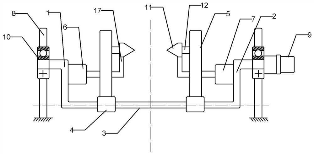
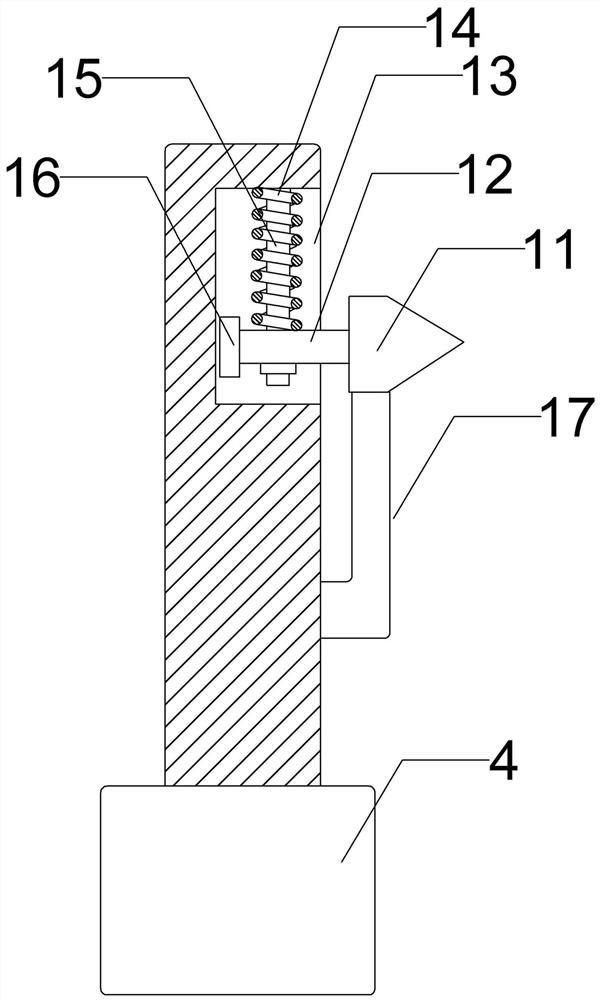
[0035] The reference signs in the accompanying drawings include: first bracket 1, second bracket 2, horizontal bracket 3, slider 4, connecting rod 5, first pressing cylinder 6, second pressing cylinder 7, fixing bracket 8, Servo motor 9 , bearing 10 , pressing cone 11 , connecting block 12 , guide groove 13 , guide column 14 , compression spring 15 , counterweight block 16 , top block 17 .

[0036] as attached figure 1 Shown: The displacement tooling for automatic welding disclosed in this embodiment includes a frame body, and the frame body includes a first bracket 1 and a second bracket 2 arranged oppositely and located between the first bracket 1 and the second bracket 2 The horizontal bracket 3, the first bracket 1 and the second bracket 2 are arranged vertically, the first bracket 1, the second bracket 2 and the horizontal bracket 3 can be integrally formed, or can be a separate structure, in this embodiment, the preferred A bracket 1, a second bracket 2 and a horizontal...

Embodiment 2

[0055] In this embodiment, the difference from the first embodiment is that the lower bottom surface of the horizontal support has an inclined surface, and the tray on the automatic welding line adopts a floating structure, which may be supported by a spring. The principle of adopting this embodiment is as follows:

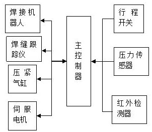
[0056] In the initial position, the horizontal support should be at a high position to avoid the conveying line and the pallet on the conveying line, so that the pallet can reach the welding station. When the workpiece to be welded reaches the welding station, the servo motor drives the first support, the second support and The horizontal bracket rotates, so that the horizontal bracket gradually turns to a low position. When it rotates to a certain angle, that is, when the pressing cone is in a relatively stable state, the main controller controls the first pressing cylinder and the second pressing cylinder to start moving toward each other. Gradually press the wo...


PUM


Abstract

The invention relates to the technical field of automatic welding, in particular to an automatic welding deflection tool which comprises a frame body, the frame body comprises a first support, a second support and a horizontal support, the first support and the second support are oppositely arranged, the horizontal support is located between the first support and the second support, and the first support, the second support and the horizontal support are driven by power to rotate on a vertical plane. A sliding rail is arranged on the horizontal support, two sliding blocks capable of sliding along the sliding rail are arranged on the sliding rail, a connecting rod is arranged on each sliding block, a pressing cone used for pressing a workpiece to be welded is arranged on the inner side of each connecting rod, and the two pressing cones can automatically adjust the pressing height in the opposite movement pressing process. The invention further provides an automatic welding system and an automatic welding assembly line based on the displacement tool for automatic welding. According to the displacement tool for automatic welding, the pressing height can be automatically adjusted so as to adapt to pressing and positioning of workpieces of different sizes, meanwhile, the positioning precision is high, and the centering effect is good.

Description

technical field [0001] The invention relates to the technical field of automatic welding, in particular to a displacement tool for automatic welding, an automatic welding system and an automatic welding assembly line. Background technique [0002] With the development of digitization, automation, computer and mechanical design technology, and the high emphasis on welding quality, automatic welding has developed into an advanced manufacturing technology, and automatic welding equipment is playing an increasingly important role in the application of various industries. The scope of application is expanding rapidly. At present, automatic welding technology has been widely used in plastics, automobile manufacturing, metal processing, hardware appliances, steel structures, pressure vessels, machining and manufacturing, shipbuilding, aerospace and other fields. After the application of automatic welding technology, the appearance and internal quality of the welded parts are great...

Claims


Application Information

Patent Timeline
IPC IPC(8): B23K37/04B23K37/02B23K37/00G01V8/12
CPCB23K37/0426B23K37/0252B23K37/00G01V8/12
Inventor 王盛学杨艳
Owner CHONGQING UNIV OF ARTS & SCI
Why Eureka
Try Eureka