

Safety type gas valve adjusting mechanism capable of achieving rapid mass production
An adjustment mechanism and safety technology, applied in combustion engines, internal combustion piston engines, valve devices, etc., can solve the problems that the product quality cannot meet customer needs, affect the stable and constant adjustment of airflow, and the adjustment of fire power is unstable. The effect of leakage accidents, reduced labor intensity of workers, and simple and ingenious structural design
- Summary
- Abstract
- Description
- Claims
- Application Information
AI Technical Summary
Problems solved by technology
Method used
Image

Examples
Embodiment 1
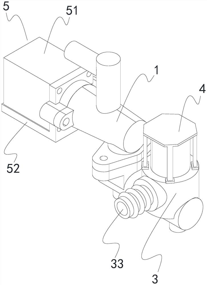
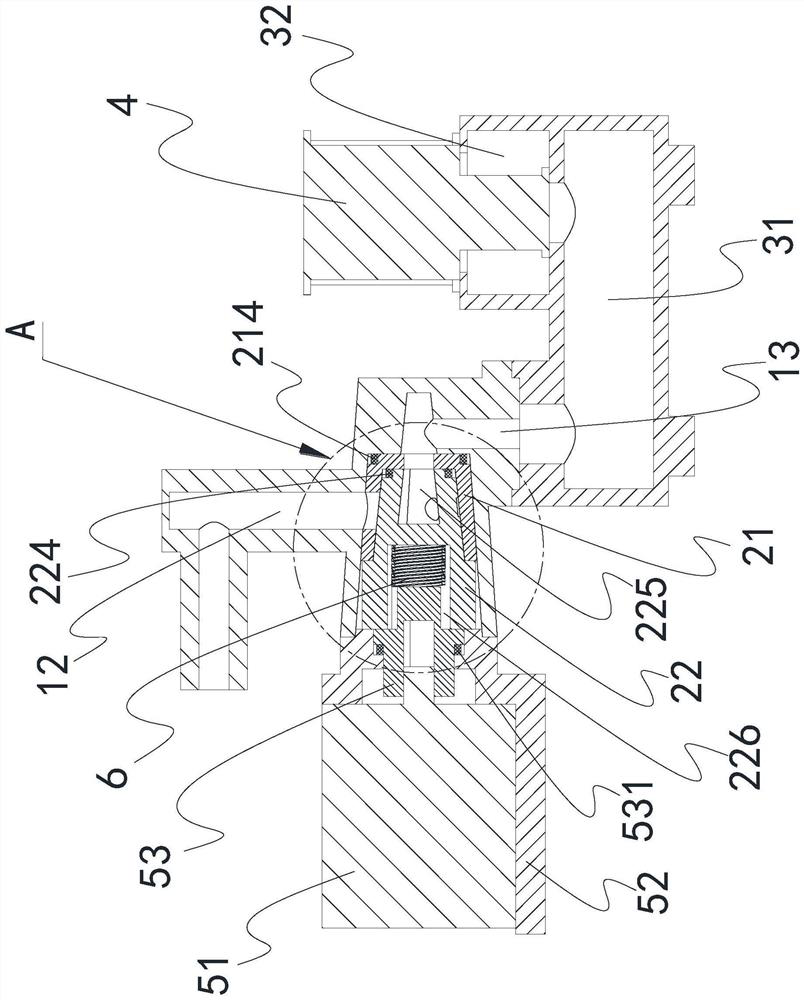
[0046] As shown in the manual Figure 1-Figure 5 As shown in the figure, a safety gas valve regulating mechanism for realizing rapid mass production includes a valve body 1, and the valve body 1 includes a valve core cavity 11 that accommodates an injection-molded valve core 2 inside, and communicates with the valve core cavity 11 and communicates with the valve core cavity 11. The valve body air outlet channel 12 towards the gas appliance is connected with the valve core cavity 11 and is the valve body air inlet channel 13 in airtight communication with the valve seat secondary main channel 31 of the valve seat 3; the valve seat 3 is also provided with a valve body The first-level main channel 32 of the valve seat is connected to the second-level main channel 31 of the seat, and the first-level main channel 32 of the valve seat is communicated with the gas pipeline through the valve seat intake channel 33; The control switch 4 for on-off between the main channel 32 and the se...
Embodiment 2
[0056] On the basis of Embodiment 1, the present invention continues to describe in detail the technical features involved and the functions and functions of the technical features in the present invention, so as to help those skilled in the art to fully understand the features of the present invention. technical solutions and reproduce them.
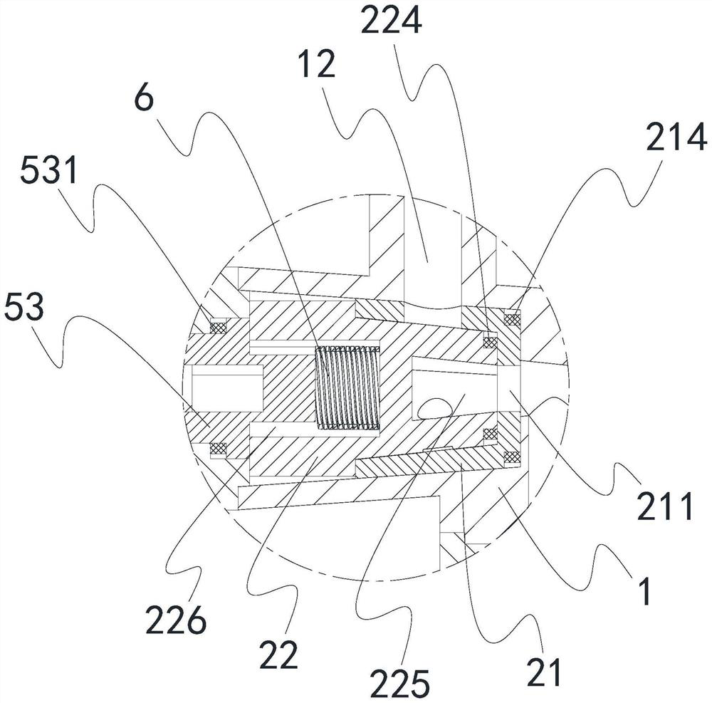
[0057] Under the action of the tensioning member 6, the limiting protruding member will closely fit with the positioning valve sleeve, so as to achieve the function of blocking the gas flow. In order to further ensure the smooth and constant regulation of the product flow, in this embodiment, grease is applied between the limiting convex piece 222 and the positioning valve sleeve 21; The small gap further ensures the constant flow regulation of the product; on the other hand, it plays a lubricating role, making the rotation of the rotary valve more flexible.
[0058] In addition to this, in this embodiment, the contact surface between ...
Embodiment 3
[0060] This embodiment is based on Embodiment 1 or Embodiment 2.
[0061] The drive unit 5 in this embodiment includes a drive element 51 and a support seat 52 supporting the drive element 51 , the support seat 52 is sealed and fixed to the valve body 1 , and the drive element 51 is a stepping motor. The sealing realization method is: use fasteners to fix the support seat 52 and the valve body 1 first, and then put sealant on the seam between the two. This is the existing conventional technology in the valve field. Repeat.
[0062] The drive element 51 drives the rotary valve 22 to move circumferentially via the rotary shaft 53 . The tensioning member 6 located in the tensioning cavity 226 squeezes the rotating shaft 53 at one end, and squeezes the rotary valve 22 at the other end; 531. The sealing ring 3 531 mainly plays a sealing role, but attention should be paid to the design of the sealing ring 3 531. It only needs an interference fit in the axial direction, because th...
PUM
 Abstract
Description
Claims
Application Information