Blue light beam combining device and blue light beam combining method based on double gratings

A dual-grating and beam technology, applied to devices for controlling laser output parameters, laser devices, semiconductor laser devices, etc., can solve problems such as insufficient number of laser light-emitting units, inability to output blue laser, and reduced beam quality, so as to improve laser output Effects of power and brightness, improvement of beam quality, and reduction of spectral interval

Pending Publication Date: 2022-08-05
UNITED WINNERS LASER CO LTD +1
View PDF0 Cites 0 Cited by
  • Summary
  • Abstract
  • Description
  • Claims
  • Application Information

AI Technical Summary

Problems solved by technology

However, in the process of spectrally combining semiconductor lasers with a grating, when a laser beam with a certain linewidth is incident on the grating, the dispersion effect of the grating will produce a diffraction effect and increase the beam divergence angle, reducing the beam quality, and When the transmission lens is long, the intermodulation of a single laser beam is caused by the increase of the overall optical path. This diffraction effect will make the beam quality decline more obvious; , it is proposed to add a transmissive grating with the same grating lines on the basis of the previous single grating to form a grating pair. This method can effectively eliminate the beam quality degradation caused by the beam passing through only one grating and the feedback crosstalk between two adjacent laser beams, but this In this way, since the beams are not compressed to reduce the beam spacing, the number of laser light-emitting units that can participate in the beam combination is insufficient and the final output power is insufficient.
[0006] At present, there are few examples of spectral beam combining of blue light semiconductor laser arrays in China, so the current beam combining equipment and methods are still unable to output blue light lasers with high power and high beam quality at the same time.

Method used


Image

  • Blue light beam combining device and blue light beam combining method based on double gratings
  • Blue light beam combining device and blue light beam combining method based on double gratings
  • Blue light beam combining device and blue light beam combining method based on double gratings

Examples


Embodiment Construction

[0066] specific implementation

[0067] In order to make the content of the present invention clearer, more concise and closer to reality, specific embodiments of the present invention will be described in detail below with reference to the accompanying drawings. It should be understood that the specific embodiments described herein are only used to explain the present invention, but not to limit the present invention. In addition, the various technical solutions involved in the specific embodiments of the present invention described below can be combined with each other as long as there is no conflict with each other.

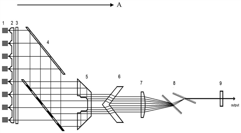
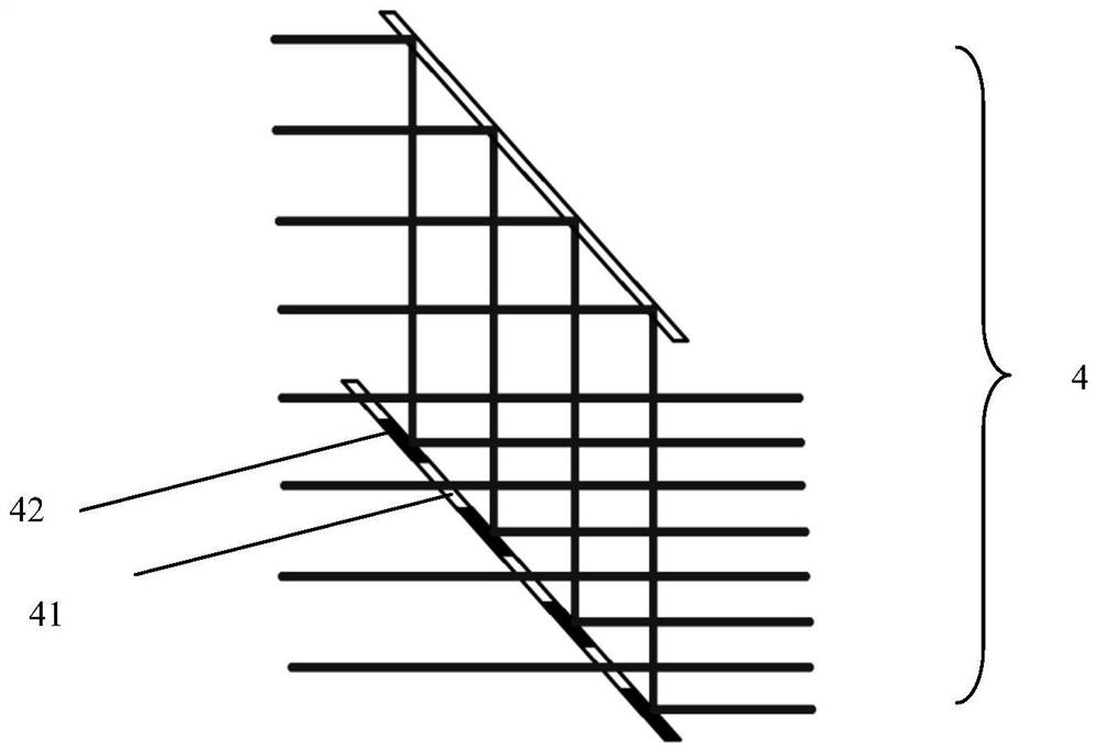
[0068] like figure 1 Shown is a schematic structural diagram of a device according to an embodiment of the present invention. The device includes a blue-light semiconductor laser array 1, a fast-axis collimating mirror 2, a slow-axis collimating mirror 3, a beam turning and compressing element group 4, a trapezoidal beam compressing element 5, Oblique beam c...


PUM

PropertyMeasurementUnit
reflectanceaaaaaaaaaa

Abstract

The invention discloses a blue light beam combining device and a blue light beam combining method based on double gratings, and relates to the technical field of laser beam combining. The device comprises a blue-light semiconductor laser array, and a fast axis collimating mirror and a slow axis collimating mirror which are provided with preset corresponding parameters, a light beam turning compression element group, a trapezoidal light beam compression element, an inclined-strip-shaped light beam compression element, a light beam deflection element, a double-diffraction grating group and an output coupling mirror which are sequentially arranged along a light path. According to the invention, the quality of blue light beams can be improved, and more light beams can be subjected to spectral beam combination.

Description

technical field [0001] The invention belongs to the technical field of blue light semiconductor lasers, and more particularly, relates to a blue light semiconductor laser array beam combining device and method based on fast and slow axis beam collimation, beam compression and double diffraction grating group spectral combining. A blue light beam combining device with double gratings and a blue light beam combining method. technical background [0002] High-power blue semiconductor lasers have unique advantages in the processing of high-reflectivity materials such as battery electrodes that power automobiles, integrated electronic components, and copper-based components used in aerospace. Since the blue-band laser does not have the problems of difficult manufacturing and welding of pure copper and copper alloys caused by the high reflectivity of infrared lasers, the application of high-power blue semiconductor lasers in the industrial field will have higher efficiency in the ...

Claims


Application Information

Patent Timeline
Patent Type & Authority Applications(China)
IPC IPC(8): H01S5/40H01S5/00H01S5/06
CPCH01S5/4012H01S5/4075H01S5/0071H01S5/0085H01S5/06
Inventor 卢国杰唐霞辉王翘张义威陈国宁赵昺旭邢鹏岳姚相杰谭浩马豪杰郭志潇宋宇燕牛增强肖瑜
Owner UNITED WINNERS LASER CO LTD
Why Eureka
Try Eureka