Wind-induced vibration piezoelectric-triboelectricity coupling energy collection device

A wind-induced vibration and energy harvesting technology, which is applied in the direction of friction generators, wind power generation, piezoelectric effect/electrostrictive or magnetostrictive motors, etc., can solve the problem of single energy conversion mode, large volume of coils and permanent magnets, vibration Frequency is not high, to achieve the effect of improving energy collection efficiency, high wind energy conversion efficiency, and increasing vibration frequency

Pending Publication Date: 2022-08-05
HANGZHOU DIANZI UNIV
View PDF0 Cites 2 Cited by
  • Summary
  • Abstract
  • Description
  • Claims
  • Application Information

AI Technical Summary

Problems solved by technology

The electromagnetic type has the disadvantages of complex structure, large volume of coils and permanent magnets
Piezoelectric type is hard and brittle due to the piezoelectric sheet, with limited bearing capacity, easy fatigue damage, and insufficient stability
[0004] In addition to various single energy harvesting forms, wind-induced vibration energy harvesters in the prior art also have a small number of composite energy harvesting forms, such as coupling electromagnetic and piezoelectric, but because the electromagnetic type is greatly affected by the environmental magnetic field, and combined with The structure of the piezoelectric type is more complicated, which is not conducive to practical application, and the voltage amplitude generated by the electromagnetic type and the piezoelectric type are difficult to couple and output in series, and the output power is limited
Therefore, the existing wind-induced vibration energy harvesters still have problems such as single energy conversion method, low utilization efficiency, low vibration frequency, low output power, narrow working wind speed range, and inability to adapt to wind direction.

Method used


Image

  • Wind-induced vibration piezoelectric-triboelectricity coupling energy collection device
  • Wind-induced vibration piezoelectric-triboelectricity coupling energy collection device
  • Wind-induced vibration piezoelectric-triboelectricity coupling energy collection device

Examples


Embodiment Construction

[0026] The present invention will be further explained below in conjunction with the accompanying drawings;

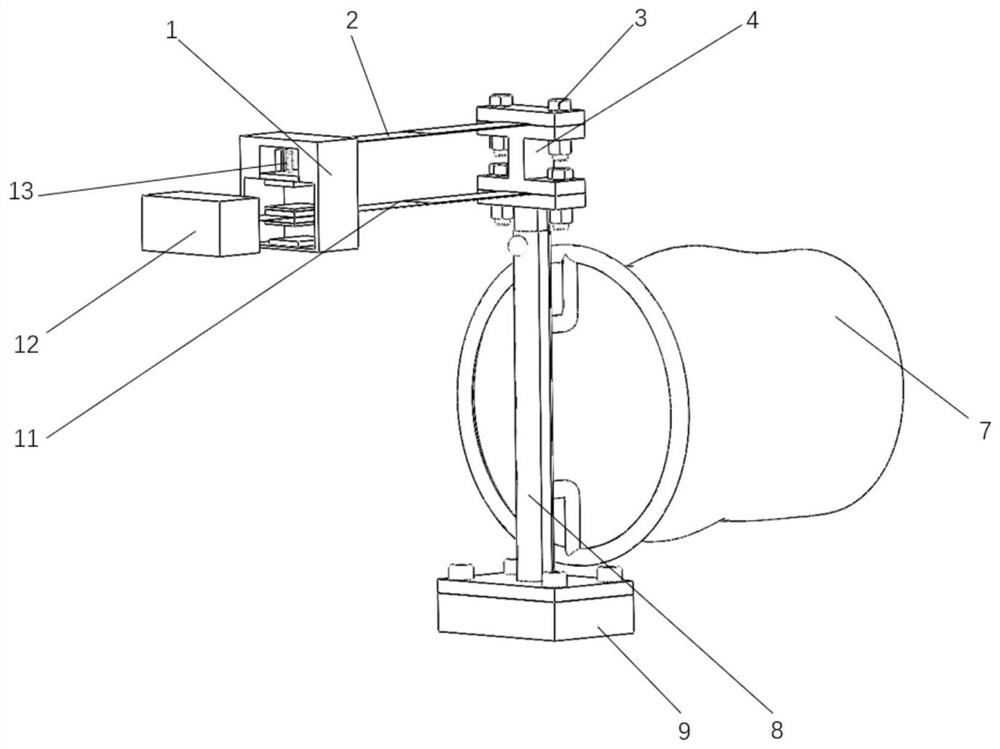
[0027] like figure 1 As shown, a piezoelectric-triboelectric coupling energy harvesting device for wind-induced vibration includes an adaptive module and a harvesting module.

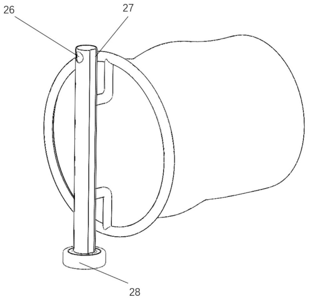
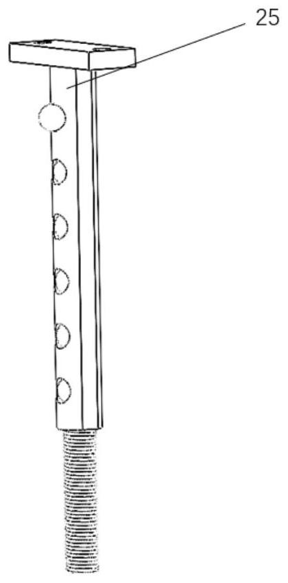
[0028] like figure 2 As shown, the adaptive module includes a fixed base 9 , a support rod and a windsock 7 . like image 3 As shown, the support rod includes a sleeve 8 and an inner rod 25 , and the inner rod 25 is arranged in the sleeve 8 and is slidably connected with the sleeve 8 . A positioning hole 26 is provided on the side of the sleeve 8 , and a plurality of limit blocks 27 extending and retracting along the width direction of the inner rod 25 are provided on the side of the inner rod 25 . The height adjustment of the support rod can be achieved through the cooperation between the positioning hole 26 on the sleeve 8 and the limit block 27 on the inner rod 25 . The fixed base 9 is ...


PUM


Abstract

The invention discloses a piezoelectric-triboelectric coupling energy collection device with wind-induced vibration. The problems that in the prior art, a wind-induced vibration energy collector is low in output power, narrow in working wind speed range and single in energy conversion form are solved. According to the invention, a double-cantilever beam structure is arranged, and piezoelectric ceramics are fixed on the surfaces of the long cantilever beam and the short cantilever beam; the rectangular bluff body is fixed at the free end of the cantilever beam; an elastic sliding block is arranged in a first bluff body fixed with the short cantilever beam; a friction material and a conductive metal layer are respectively fixed on the opposite surfaces of the long cantilever beam and the first bluff body; the fixed end of the double-cantilever beam and the supporting rod are fixed by a plurality of jump springs; a wind direction bag is fixed to the pipe sleeve and forms a rotating pair with the fixed base. The collecting device can be adjusted in a self-adaptive mode and is parallel to the wind direction all the time, the wind energy utilization rate is increased, the vibration frequency is improved, meanwhile, high potential difference is generated through piezoelectric ceramics and friction materials, and the energy output power of the device is improved.

Description

technical field [0001] The invention belongs to the technical field of energy collection, and in particular relates to a piezoelectric-triboelectric coupling energy collection device of wind-induced vibration. Background technique [0002] With the application and development of micro-electromechanical systems (MEMS) in medical and health, industrial production and other fields, new requirements are also put forward for energy supply. Using batteries to power equipment will not only hinder the long-term work of the equipment, but also waste batteries after use can easily cause great pollution to the environment. However, there are various forms of abundant resources in the natural environment that can be used for energy supply, such as wind energy, solar energy, magnetic energy, etc. Therefore, it has become an emerging development direction to make up for the power gap caused by scientific and technological development through the collection and application of environmental...

Claims


Application Information

Patent Timeline
Patent Type & Authority Applications(China)
IPC IPC(8): H02N1/04H02N2/18
CPCH02N1/04H02N2/186Y02E10/72
Inventor 周茂瑛罗韦昊朱宗明黄世帆徐振龙王班秦华伟
Owner HANGZHOU DIANZI UNIV
Why Eureka
Try Eureka