Cell-microbead pairing capture method applied to unicellular omics analysis
A single-cell, cell-based technology, applied in the direction of sterilization methods, chemical instruments and methods, biochemical equipment and methods, etc., can solve the problems of cross-contamination of capture structures, large sample consumption, complex structures, etc., and achieve low cost, Ease of operation and high capture efficiency
- Summary
- Abstract
- Description
- Claims
- Application Information
AI Technical Summary
Problems solved by technology
Method used
Image
Examples
Embodiment 1
[0037] Example 1 A cell-microbead paired capture method
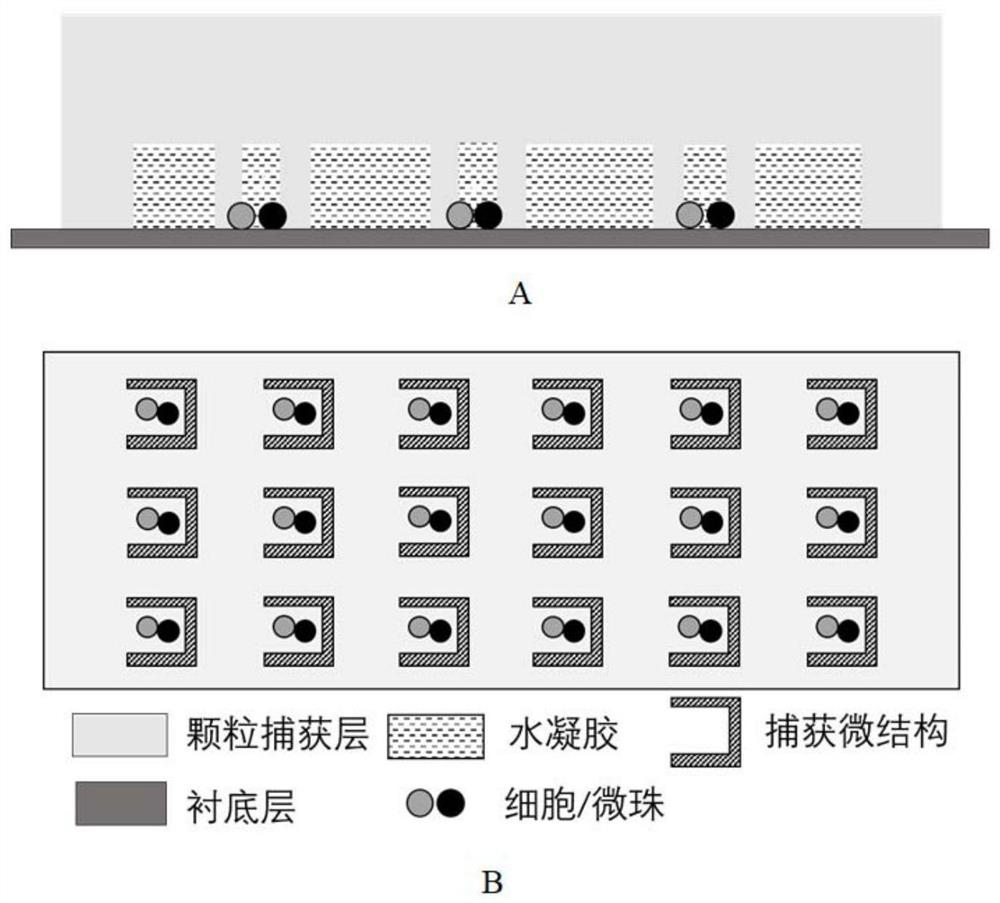
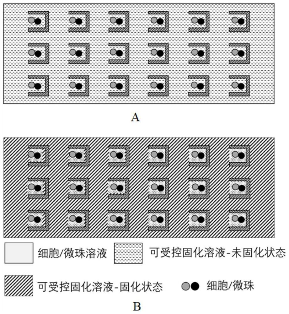
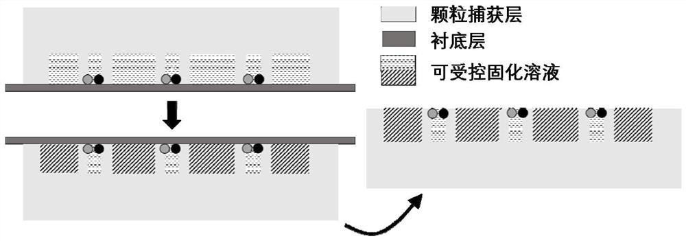
[0038] combine Figure 1 to Figure 3 As shown, a cell-microbead paired capture method provided according to a preferred embodiment of the present invention is shown, comprising the following steps:
[0039] S1: First provide a figure 1 The microfluidic capture device shown, the microfluidic capture device is composed of a particle capture layer and a substrate layer, and the two layers can be separated; the particle capture layer is provided with an inlet, an outlet, and one-to-one paired capture cells - Several capture microstructures of the microbeads distributed in an array.
[0040] S2: Pass the cell suspension and microbead suspension into the particle capture layer sequentially from the inlet, and realize the capture of a single cell and a single microbead in sequence in the capture microstructure, thereby forming a large-scale cell-bead paired array .
[0041] S3: After the paired capture is completed, contro...
Embodiment 2
[0051] Embodiment 2 A microfluidic capture device and cell-microbead paired capture method
[0052] combine Figure 4 to Figure 5 As shown, a microfluidic capture device provided according to this preferred embodiment is shown, and the microfluidic capture device can capture cells-microbeads by a hydrodynamic method, and the detailed description is as follows:
[0053] The microfluidic capture device is composed of a particle capture layer and a substrate layer, and the two layers can be separated. like Figure 4 As shown, the particle capture layer sequentially includes from upstream to downstream: an inflow zone 1 , a capture zone 2 , and an outflow zone 3 .
[0054] The inflow area 1 includes: an inlet 4 , a branch channel 5 , and a pre-filter 6 . The inlet 4 is connected with several runners 5 of equal width. The runner 5 is symmetrical with the third channel 7 as the axis of symmetry. At the same time, a section is reserved at the rear end of the inflow area 1 to form ...
Embodiment 3
[0067] Example 3 Preparation of a Microfluidic Capture Device
[0068] According to this preferred embodiment, the present invention also provides a preparation method of a microfluidic capture device, the processing flow is as follows Figure 9 shown, the detailed description is as follows:
[0069] (1) Design and production of photolithography masks: draw the design diagram of the microfluidic device, and use high-precision printing to output multiple masks. A pattern is formed in the exposure step.
[0070] (2) Photolithography to prepare mold
[0071] Photolithography is micro-manufacturing with photoresist, mask and ultraviolet light, and the mold processing can be repeated and used. The specific process is as follows:
[0072] ①Clean the silicon wafer
[0073] ②Soft bake
[0074] ③Exposure: place the mask on the top of the silicon wafer, irradiate the silicon wafer with the photoresist spin-coated with ultraviolet light, the photoresist undergoes a photochemical react...
PUM
 Abstract
Description
Claims
Application Information
 - R&D
- Intellectual Property
- Life Sciences
- Materials
- Tech Scout
- Unparalleled Data Quality
- Higher Quality Content
- 60% Fewer Hallucinations
Browse by: Latest US Patents, China's latest patents, Technical Efficacy Thesaurus, Application Domain, Technology Topic, Popular Technical Reports.
© 2025 PatSnap. All rights reserved.Legal|Privacy policy|Modern Slavery Act Transparency Statement|Sitemap|About US| Contact US: help@patsnap.com


