
Continuous feeding mechanism of sheet inserting machine

A feeding mechanism and inserting machine technology, which is applied in the direction of conveyor objects, climate sustainability, sustainable manufacturing/processing, etc., can solve the problems of slow feeding cycle, high labor cost and procurement cost, low fault tolerance rate, etc. , to achieve the effect of reducing the cost of employment, high degree of intelligent manufacturing, and reducing procurement costs

Pending Publication Date: 2022-08-09
无锡市南亚科技有限公司
View PDF0 Cites 0 Cited by
  • Summary
  • Abstract
  • Description
  • Claims
  • Application Information

AI Technical Summary

Problems solved by technology

[0003] The purpose of the present invention is to provide a continuous feeding mechanism for a chip inserter, which can effectively overcome the defects of the existing solar silicon chip chip inserter equipment, such as slow feeding rhythm, high labor cost and procurement cost, and low fault tolerance rate. criticize

Method used


Image

  • Continuous feeding mechanism of sheet inserting machine
  • Continuous feeding mechanism of sheet inserting machine
  • Continuous feeding mechanism of sheet inserting machine

Examples


Embodiment Construction

[0021] It should be noted that the embodiments of the present invention and the features of the embodiments may be combined with each other under the condition of no conflict. The present invention will be described in detail below with reference to the accompanying drawings and in conjunction with the embodiments.

[0022] In order for those skilled in the art to better understand the solutions of the present invention, the technical solutions in the embodiments of the present invention will be clearly and completely described below with reference to the accompanying drawings in the embodiments of the present invention. Obviously, the described embodiments are only Embodiments of some, but not all, of the present invention. Based on the embodiments of the present invention, all other embodiments obtained by persons of ordinary skill in the art without creative efforts shall fall within the protection scope of the present invention.

[0023] It should be noted that the terms ...


PUM


Abstract

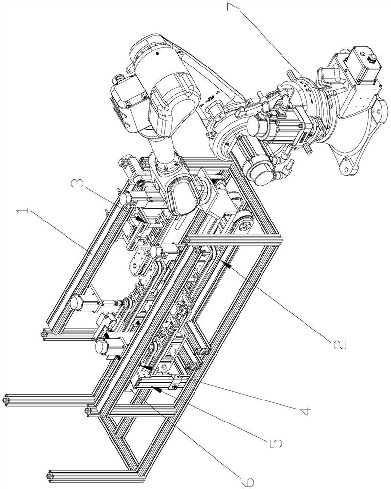
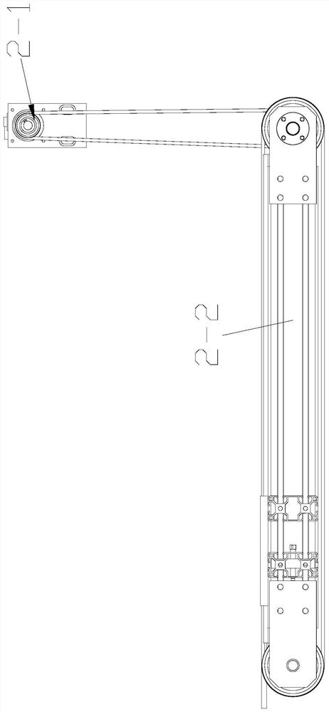
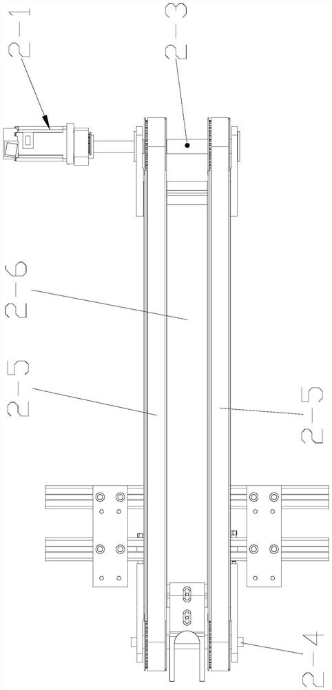
The invention relates to a continuous feeding mechanism of a wafer inserting machine. The continuous feeding mechanism comprises a frame, a silicon wafer conveying line and a bearing and dragging platform are installed in the frame, a silicon wafer feeding and clamping mechanism is arranged above the silicon wafer conveying line, a silicon wafer feeding and righting mechanism is arranged on one side of the silicon wafer feeding and clamping mechanism, and water jet cutters are installed on the two sides of the silicon wafer feeding and righting mechanism; one end of the bearing and dragging platform clings to the end part of the silicon wafer conveying line; the silicon wafer conveying line comprises a conveying motor and a conveying frame, a driving conveying shaft and a driven conveying shaft are horizontally and rotationally installed at the two ends of the conveying frame, the driving conveying shaft and the driven conveying shaft are connected through a conveying belt, and the conveying motor drives the driving conveying shaft. The device is simple in structure and small in occupied space; and the device is safe, environment-friendly, simple and reliable in structure. The later equipment structure maintenance cost is low; and unmanned production can be really achieved in cooperation with a truss or a six-axis mechanical arm, and the intelligent manufacturing degree is high. And the labor cost is reduced.

Description

technical field [0001] The invention belongs to the technical field of new energy solar photovoltaic, and relates to a continuous feeding mechanism of a chip inserter. Background technique [0002] In the modern photovoltaic solar wafer production line, a special machine is used - a fully automatic wafer insertion machine. Due to the current technological requirements of silicon wafers, in the production process, the feeding process is manually taken out from the degumming machine to arrange the silicon wafers and then put them into the inserter box for inserting. The current process equipment does not realize fully automatic feeding. . At present, the manual feeding rhythm is slow, the labor cost and procurement cost are high, and the fault tolerance rate is low. SUMMARY OF THE INVENTION [0003] The purpose of the present invention is to provide a continuous feeding mechanism for a wafer inserter, which can effectively overcome the shortcomings of the existing solar wa...

Claims


Application Information

Patent Timeline
Patent Type & Authority Applications(China)
IPC IPC(8): H01L21/677H01L31/18B65G47/90
CPCH01L21/67706H01L21/67736H01L31/1804B65G47/90B65G2201/02Y02P70/50
Inventor 顾韻
Owner 无锡市南亚科技有限公司
Learn More