Wheel type hydraulic drifting machine

A well drilling machine and hydraulic technology, applied in wellbore/well parts, earthwork drilling and production, etc., can solve the problems of transmission system and main drawworks drum failure, high maintenance cost, low installed power, etc., and shorten the operation preparation time , Braking is safe and reliable, and the effect of prolonging the service life

Inactive Publication Date: 2005-07-13
SHENGLI OIL FIELD SHENGLI POWER MACHINERY GRP
View PDF0 Cites 0 Cited by
  • Summary
  • Abstract
  • Description
  • Claims
  • Application Information

AI Technical Summary

Problems solved by technology

The crawler-type well drilling machine was originally introduced from the former Soviet Union. It is an operation equipment refitted on the chassis of a crawler tractor. Judging from the current use, it has the following disadvantages: 1. Poor transportation performance and long preparation time
Since the driving speed is generally lower than 10km / h, and it is not allowed to drive on the road, it must be transported to the well site by a trailer. The moving period is long and the cost is high.
2. The transmission method adopts mechanical transmission, and the power utilization rate is low
The transmission system and the main winch drum often fail due to the impact load during frequent lifting operations
3. The installed power is small, the lifting speed is slow, the operation efficiency is low, and the ability to deal with accidents is poor
However, the existing wheeled well drilling machines all use hydraulic torque converter transmission, which realizes the flexible transmission of power, and is stepless speed regulation within a certain range.
However, from the perspective of overall efficiency, there are disadvantages such as low power utilization and high fuel consumption.
In addition, the above-mentioned two kinds of hoisting machines both use free-falling hooks when lowering heavy objects, and the speed control of heavy objects is realized by using sliding brakes with band brakes. The friction plates wear quickly, frequent replacement, and high maintenance costs.

Method used


Image

  • Wheel type hydraulic drifting machine
  • Wheel type hydraulic drifting machine

Examples


Embodiment Construction

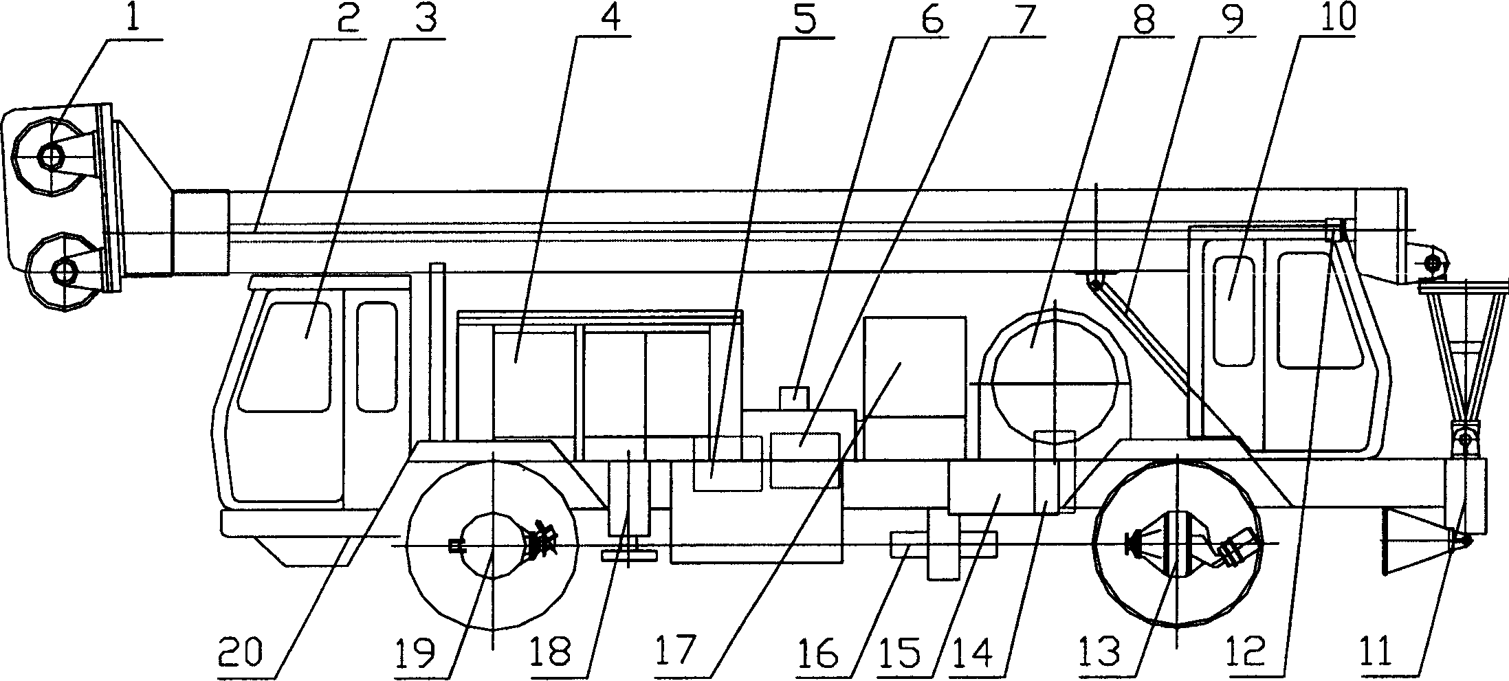
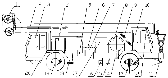
[0007] Below in conjunction with accompanying drawing, the present invention is described in further detail: referring to accompanying drawing, wheeled hydraulic well drilling machine is made up of engine 4, driver's cab 3, operating room 10, hydraulic oil tank 17 and operating system, walking part and operation part etc., The walking part has a chassis 20, a front drive axle 19 and a rear drive axle 13; the working part has a crane 1, a derrick 2 and a hydraulic lifting control system, and the derrick 2 is lifted by a hydraulic control cylinder, which is composed of a hydraulic cylinder 12 and a lifting control system. Liter oil cylinder 9 forms. The hydraulic transmission system transmits the power of the engine 4 to the gearbox 16, and the gearbox 16 transmits the power to the walking part and the working power transmission mechanism respectively. The hydraulic transmission system consists of a hydraulic pump 5 , a main valve block 6 , and a hydraulic motor 7 . The engine 4...


PUM


Abstract

The invention discloses a wheeled hydraulic well drilling machine used in the petroleum and natural gas industry, which is suitable for operations such as salvaging oil, water and gas wells, inspecting pumps and testing oil. The invention includes an engine, a cab, an operating room, a hydraulic oil tank and an operating system, a traveling part and an operating part, the traveling part has a chassis, a front drive axle and a rear drive axle; the working part has a crown block, a derrick and a hydraulic lifting control system, The derrick is lifted by a hydraulic control cylinder. The hydraulic transmission system transmits the power of the engine to the gearbox, and the gearbox transmits the power to the walking part and the working power transmission mechanism respectively. The hydraulic transmission system has a hydraulic pump, a main valve block and a hydraulic motor. The engine drives the hydraulic pump to transmit high-pressure oil to the hydraulic motor through the main valve block, and the hydraulic motor is connected to the gearbox. The transmission structure is simplified, and the gear box has fewer gears and is easy to manufacture. Using hydrostatic drive technology and its own mast type derrick, it shortens the preparation time for operation.

Description

technical field [0001] The invention relates to workover equipment in the petroleum and natural gas industry, in particular to a wheeled hydraulic well drilling machine, which is suitable for operations such as salvaging oil wells, water injection wells, and gas wells, inspecting pumps, installing wellhead equipment, and testing oil. technical background [0002] Well drilling machines currently used in oil and gas fields include crawler drilling machines and wheel drilling machines. The crawler-type drilling machine was originally introduced from the former Soviet Union, and it is an operation equipment refitted on the chassis of a crawler tractor. Judging from the current use, it has the following disadvantages: 1. Poor transportation performance and long preparation time for operations. Since the driving speed is generally lower than 10km / h, and it is not allowed to drive on the road, it must be transported to the well site by a trailer. The moving period is long and the ...

Claims


Application Information

Patent Timeline
Patent Type & Authority Patents(China)
IPC IPC(8): E21B41/00
Inventor 陈宜亮王学军翟惠宁商上海王红占
Owner SHENGLI OIL FIELD SHENGLI POWER MACHINERY GRP
Why Eureka
Try Eureka