Micromechanical optical switch made of metal material

An optical switch and micro-mechanical technology, applied in optics, light guides, optical components, etc., can solve the problems of limited size of micro-mirrors, low reflection coefficient and high difficulty, and achieve the effect of simple unit structure, good scalability and simple control.

Inactive Publication Date: 2005-09-28
CHONGQING UNIV +1
View PDF0 Cites 0 Cited by
  • Summary
  • Abstract
  • Description
  • Claims
  • Application Information

AI Technical Summary

Problems solved by technology

[0004] However, the current mainstream technologies of MEMS optical switches are bulk silicon technology and surface micromachined silicon technology. In order to ensure the performance of optical switches, complex process processing is required, resulting in complicated MEMS optical switch processes and poor compatibility with IC processes. Problems such as low yield rate also lead to an increase in the cost of the unit optical switch
[0005] At the same time, the current MEMS optical switch micromirror is usually made of polycrystalline silicon material (prepared by surface micromachining technology) or single crystal silicon (prepared by bulk silicon process technology). Deformation of the mirror surface requires a complicated process to remove the stress of the polysilicon layer and avoid deformation. It is very difficult to implement, and the process complexity and cost will increase significantly, and the yield rate is not high; The surface finish cannot be guaranteed, and the shape of the mirror surface is not easy to control, and the size of the micromirror is also severely limited, and the single crystal silicon is directly used as a mirror surface for reflection, and its reflection coefficient is low, resulting in a large insertion loss of this type of optical switch. The micromirror of materials is quite difficult in the process and practical research

Method used


Image

  • Micromechanical optical switch made of metal material
  • Micromechanical optical switch made of metal material
  • Micromechanical optical switch made of metal material

Examples


Embodiment Construction

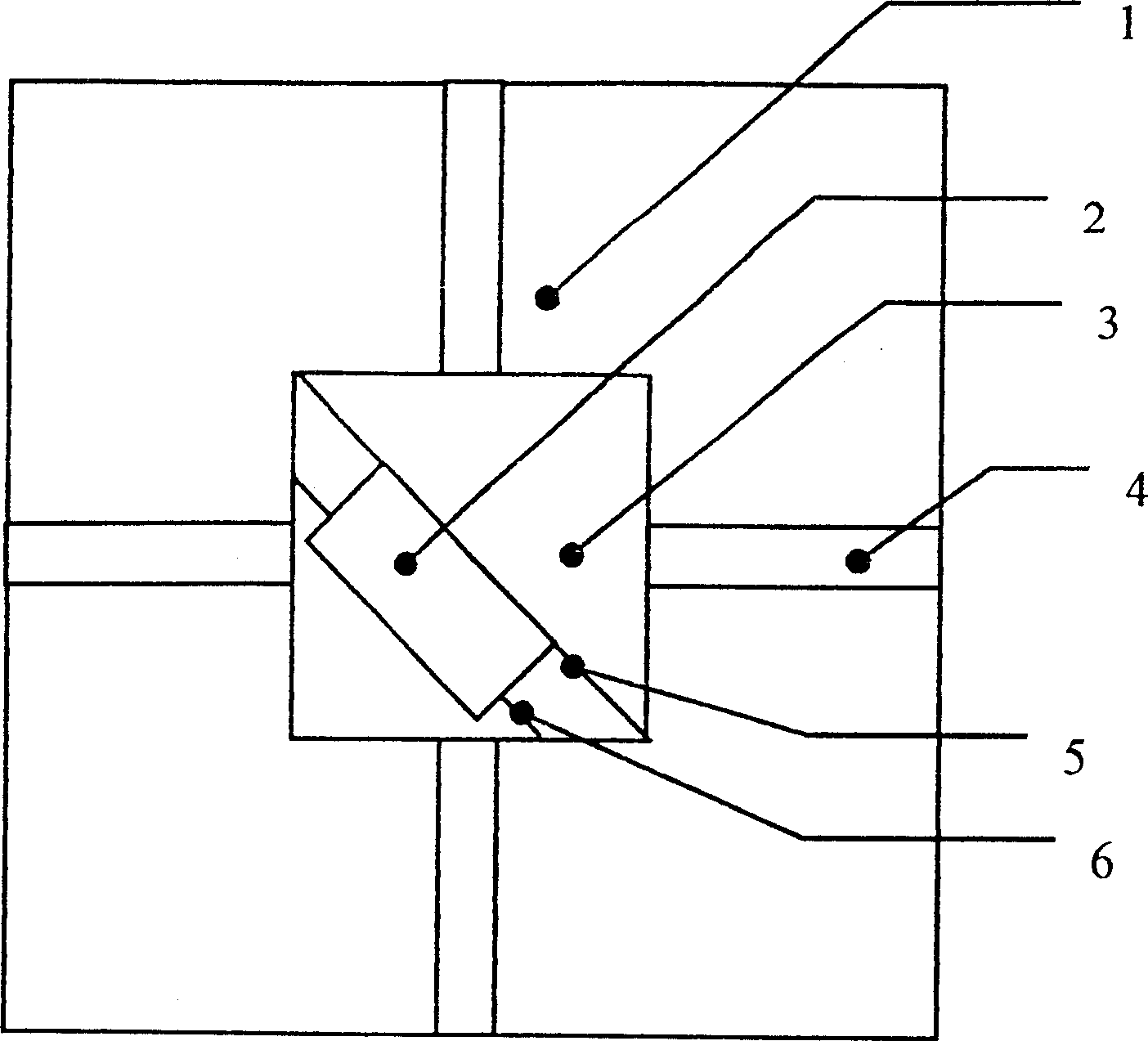
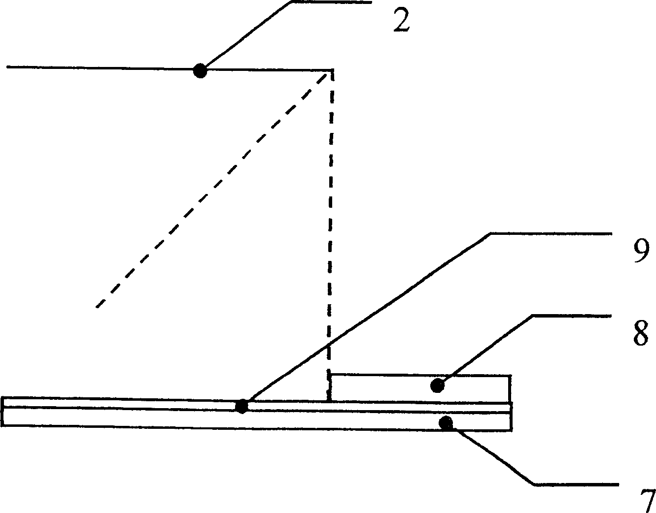
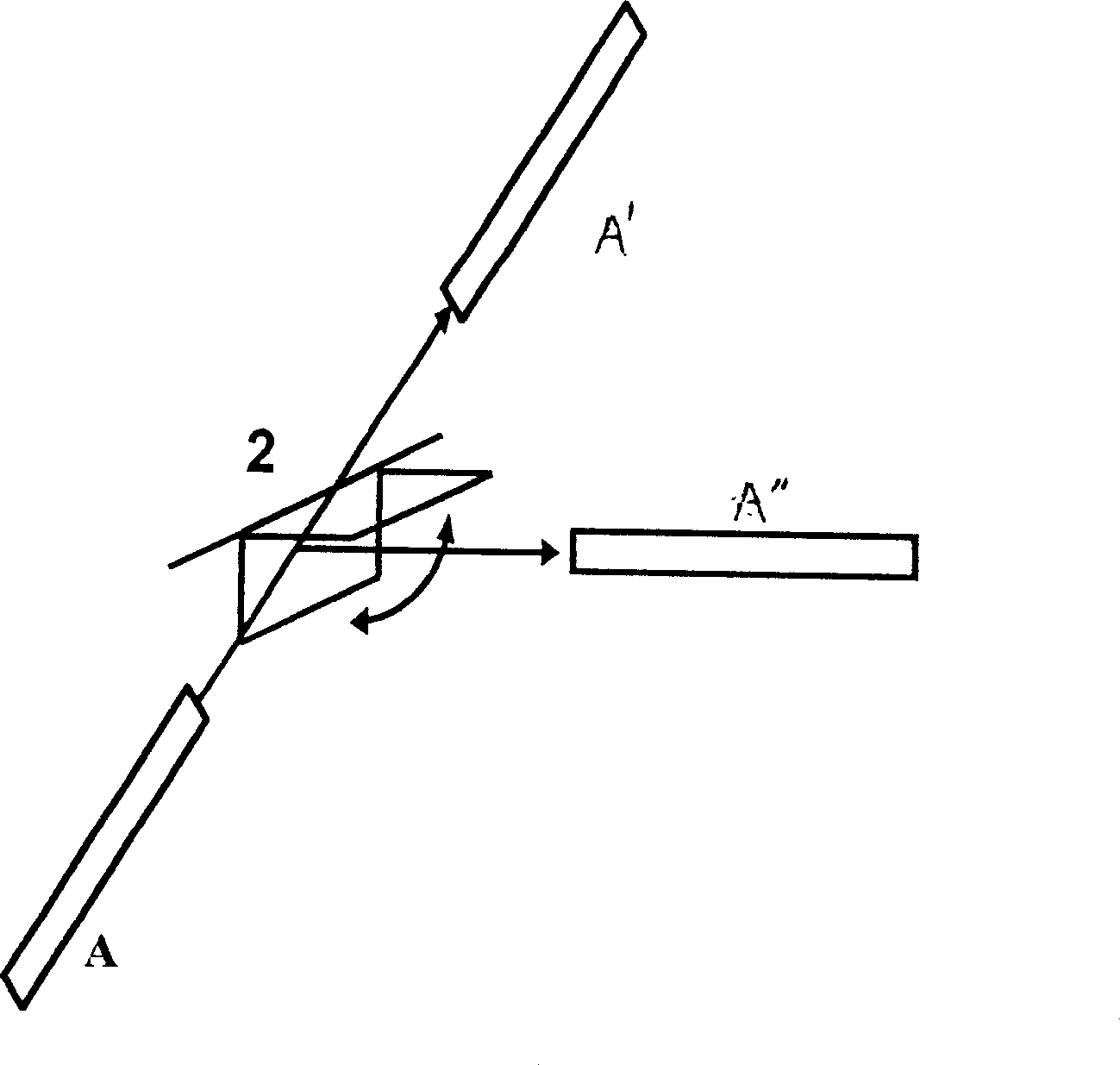
[0026] see figure 1 and figure 2 , the optical switch is composed as follows: a substrate 1 formed by a silicon wafer, a micromirror 2, a through hole 3, a V-shaped groove 4, a double-sided cantilever beam 5, a temporary support beam 6, a lower electrode 7, a micromirror stop structure 8 and The anti-breakdown layer 9 consists of several parts. The micromirror 2 is a twistable horizontal structure, made of various metal alloy materials, and also serves as an upper electrode. Directly below the micromirror 2 is a through hole 3 whose depth is slightly greater than the length of the micromirror. The double-sided cantilever arm 5 is supported on both sides of the micromirror 2, and is a rectangular cantilever beam, which is formed by the same metal mask as the micromirror. The lower electrode 7 is formed by sputtering metal on the silicon chip at the lower part of the through hole 3, and together with the upper electrode formed by the micromirror 2, forms an electrostatically...


PUM


Abstract

The switch consists of base plate, micromirror, through-hole V-shape slot, over hanging beam at two sides, temporary supporting beam, bottom electrode stop device and breakdown proof layer, of which the micromirror is designed in level structure with metal material. Its over hanging beam at two sides can be turned to make the micromirror rotate to be vertical state for inserting into light path through driving of static electricity so that the switching function to change light path is realized. It can be used to fabricate 1X1, 1X2, 2X2... NXN type of MEMS light switch and array.

Description

technical field [0001] The invention relates to a micromechanical optical switch made of metal materials, which belongs to the field of optoelectronic devices. Background technique [0002] With the advent of the Internet age, people's demand for information is increasing day by day. The rapid development of IP services in the global scope has not only brought a huge impact on traditional telecommunication services, but also provided new opportunities for the development of telecommunication networks. Judging from the current trend of information technology development, building a high-speed and large-capacity broadband integrated service network has become an inevitable trend in the development of modern information technology. In recent years, the development of Dense Wavelength Division Multiplexer (DWDM: Dense Wavelength Division Multiplexer) technology has provided an effective way to utilize the bandwidth of optical fiber, and has made outstanding progress in point-to...

Claims


Application Information

Patent Timeline
Patent Type & Authority Patents(China)
IPC IPC(8): G02B6/136G02B6/35
Inventor 罗元张正元黄尚廉徐世六
Owner CHONGQING UNIV
Why Eureka
Try Eureka