Rolling mill for wire rod material and tandem mill set

A technology for rolling mills and wire rods, applied in the field of on-line bar rolling mills and continuous rolling mills, can solve the problems of complex and large structures, large vibrations, and difficulty in realization, and achieve the effects of simplified precision adjustment, easy processing, and easy manufacturing

Inactive Publication Date: 2006-08-30
方崇实 +1
View PDF0 Cites 0 Cited by
  • Summary
  • Abstract
  • Description
  • Claims
  • Application Information

AI Technical Summary

Problems solved by technology

[0014] 1. Generally, there is no adjustment device for the rolls in the radial and axial directions;
[0015] 2. The roll sheet cannot be loaded and unloaded conveniently, and after the roll sheet is worn, it must be processed in the rolling mill frame with a special machine tool;
[0016] 3. The bevel gear in the machine should be lubricated with thin oil, which has complicated sealing problems, and the line speed of this rolling mill should be limited below 30 m / s;
[0017] 4. In general, the speed of each stand of a multi-stand continuous rolling mill cannot be adjusted. It is actually impossible to implement a kind of micro-tension rolling for different steel types. Even if the width is limited, the difference in width of different steel types is still very large.
[0025] 6. Thin decarburization layer;
[0028] 1. The price is too high for users to bear;
[0029] 2. The vertical part of the C-type transmission box adopts close-packed cylindrical gears, resulting in complex and huge structure, difficult processing and many processing procedures;
[0031] 4. The collective centralized adjustment of bevel gears between eccentric sleeves is still retained, that is, the flexible rolls are driven independently but the radial adjustment still lacks freedom, causing mutual interference, and bringing great inconvenience to manufacturing, installation, and adjustment, limiting three rolls Possibility of drastic adjustment of pass pattern
[0033] 1. The structure of the working frame is complex, and it uses at least 24 rolling bearings, which is twice that of the traditional KOCKS rolling mill. There are also spline connections inside the transmission gear, which weakens the strength of the frame and increases the difficulty of thin oil lubrication and sealing;
[0034] 2. The roll clamping method shown in Figure 8 is both complicated and wastes roll material, and is not suitable for high wear-resistant and brittle rolls such as tungsten carbide rolls. The rolling torque of Φ46~Φ50 round steel with 20% compression rate is very high;
[0035] 3. Figure 5 The roll radial adjustment scheme shown is very difficult to use and difficult to realize. If the worm, hydraulic motor, encoder, and gear are damaged, the two halves of the frame must be disassembled. For a small three-roll mill such as a roll with a diameter of 210mm, the space in the frame Can't fit these devices
Radial adjustment does not have the function of manual adjustment
[0036] 4. No roll axial adjustment device is designed
[0038] 1. The price of KOCKS rolling mill is much higher than that of two-roll rolling mill;
[0039] 2. The spare parts of KOCKS rolling mill are large;
[0042] 5. The KOCKS mill one-sidedly emphasizes collective transmission and compactness, which limits the scope of use
In the 5857371 patent, the motor suspension and transmission suspension are only suitable for small-sized rolling mills and non-ferrous metals. For large-scale rolling mills, this solution is obviously not suitable. The motor and transmission equipment weighing several tons or even tens of tons are running at high speed. when the vibration is great
In addition, when producing high-alloy steels with many varieties, high strength, low plasticity, and large differences in width and width, KOCKS rolling mills are collectively driven, and relying solely on micro-opening rolling has many problems. The speed of each rolling mill cannot be adjusted and is only suitable for a single steel. kind of rolling

Method used


Image

  • Rolling mill for wire rod material and tandem mill set
  • Rolling mill for wire rod material and tandem mill set
  • Rolling mill for wire rod material and tandem mill set

Examples


specific Embodiment approach

[0075] Specific implementation method (only in the form of continuous rolling, without involving the use of reversible Y-type rolling for billet opening and rough rolling):

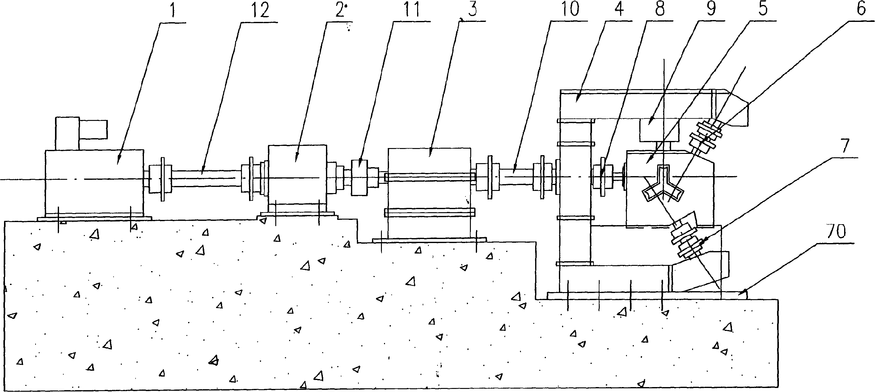
[0076] figure 1 4 is the C-type transmission box, and 5 is the working stand of the rolling mill. C The power of the type transmission box 4 is transmitted to the rolling mill 5 respectively, and the C type transmission box is fixed on the base 70. Coupling 10 transmits power to the linkage box, 1 is the main motor, and power is transmitted to the planetary reducer through coupling 12, and 9 is the hydraulic system for fixing the working stand of the rolling mill.

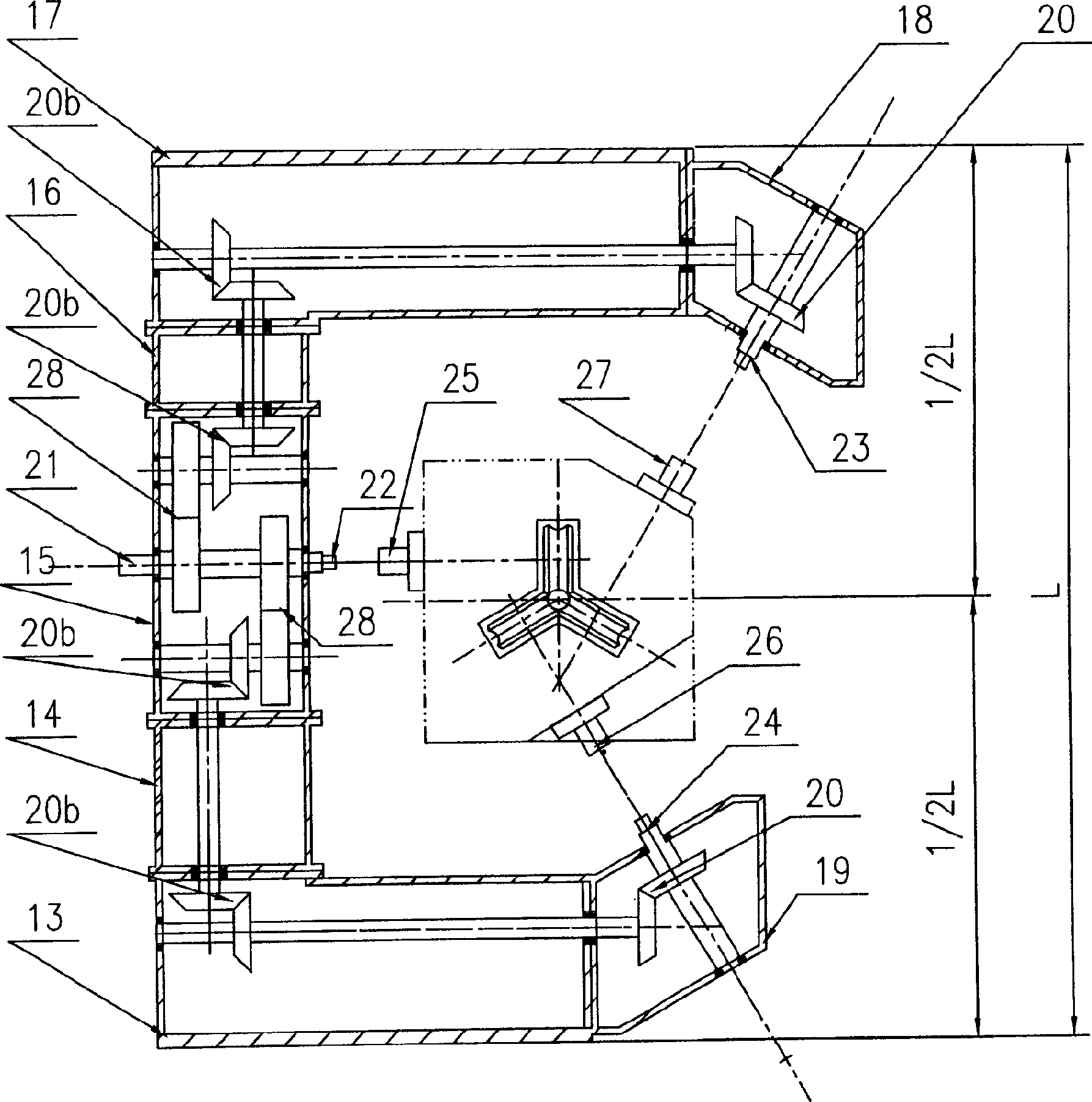
[0077] figure 2 It is a new Y-type three-roll mill C-type transmission box, and its box body is composed of horizontal box bodies 13, 17 with mounting holes, main box bodies 14, 15, 16 and inclined box bodies 18, 19 and other seven bolts (not shown). 20, 20b, 28 represent 8 pairs of gear trains that divide the main transmission into three...


PUM


Abstract

A rolling mill for rolling wire or rod material is composed of a Y-type three-roller rolling set and a combined C-type drive case for driving three roller lines via input shaft, gear train and bidirectional clutch system. The roller can be radially regulated by hydraulic motor, encoder, gear and worm, or be axially regulated by screw sleeves. A pull rod applies pretightening force for clamping roller sheet by super-class bolts. The roller bearing uses labyrinth seal and gas seal. A tandem mill set is also disclosed for creating a production line.

Description

technical field [0001] The invention relates to a Y-shaped three-roller hot rolling mill for metal wire and bar, which relates to the independent drive and independent radial and axial adjustment of the three roll systems of the working stand of the rolling mill, relates to the C-type transmission box of the rolling mill, and relates to the same specifications of the rolling mill. Interchangeability, involving the telescopic toothed connection system corresponding to the C-type transmission box of the rolling mill and the working stand of the rolling mill, involving the roll system roll sheet clamping system and the sealing method of the roll bearing, and involving the connection of all C-type transmission boxes and the working stand of the rolling mill The integrated frame system relates to the combination of various continuous rolling units of the rolling mill. Background technique [0002] The Y-shaped three-roller bar mill is called KOCKS rolling mill in foreign countrie...

Claims


Application Information

Patent Timeline
Patent Type & Authority Patents(China)
IPC IPC(8): B21B13/10B21B1/18B21B13/08B21B27/02
Inventor 方崇实方钧
Owner 方崇实
Why Eureka
Try Eureka