Process for preparing optical fibre based on single-mode optical fibre to implement different performance of acousto-optic filter
A single-mode optical fiber and filter technology, which is applied in the field of optoelectronics, can solve the problems of limited room for design, limited acousto-optic coupling coefficient, and low degree of overlapping of sound waves and light waves, etc., to reduce power consumption, reduce device volume, Effect of Coupling Conversion Efficiency Improvement
- Summary
- Abstract
- Description
- Claims
- Application Information
AI Technical Summary
Problems solved by technology
Method used
Image
Examples
Embodiment 1
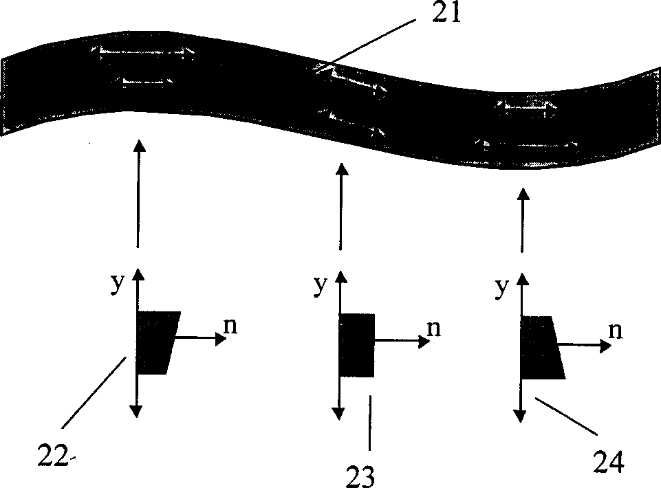
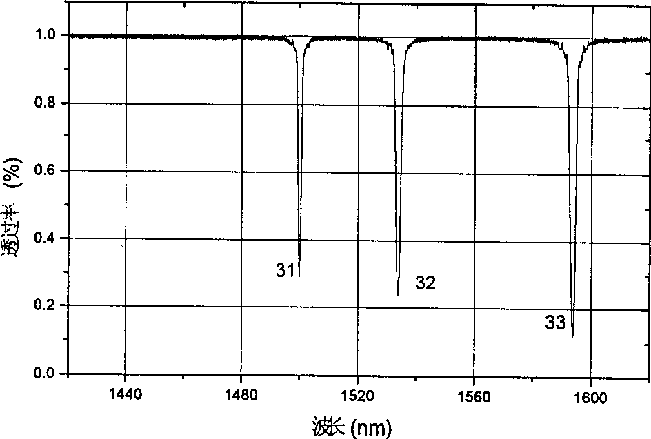
[0041] The outer diameters of the three sections of cladding matching single-mode optical fiber were partially etched to 72 μm, 56 μm and 25 μm respectively by chemical etching method, and the lengths of the etched sections were all 8 cm. The design method of the outer diameter of the etched optical fiber is: calculate the N value from formula (5) according to the required bandwidth and the allowable active area length, and then use Figure 6 The corresponding curve determines the outer diameter of the etched fiber. The optical fiber used had an original outer diameter of 125 μm, a core diameter of 8.3 μm, and a refractive index difference between the core region and the cladding region of 0.33%. Using hydrofluoric acid with a concentration of about 40%, the etching rate is calibrated at room temperature to be about -60 μm / 30 minutes, and then the etching time is controlled to obtain the required outer diameter of each optical fiber. use Figure 4 The filtered spectra measur...
Embodiment 2
[0045] A section of cladding-matched single-mode fiber identical to that used in Example 1 is partially etched with an outer diameter to 21 μm (by Figure 6 It can be seen that LP 01 -LP 11 cl The critical value of the mode is about 19.5 μm), and the length of the etched segment is 5.5 cm. use Figure 4 The filtered spectrum obtained by the experimental method shown is shown in Figure 8 . The frequency of the sound wave used is 867kHz, the voltage of the piezoelectric ceramic is 2.4V, the power consumption is about 1.1mW, and the measured bandwidth is 349nm.
[0046] It can be seen that when the outer diameter is etched to the vicinity of the critical value, the resulting filtering bandwidth increases by an order of magnitude.
Embodiment 3
[0048] The outer diameter of a section of dispersion compensating optical fiber was locally etched to 50 μm by the same method as in Example 1, and the length of the etched section was 8 cm. The fiber has an original outer diameter of 125 μm and a dispersion of 80 ps / nm / km. use Figure 4 The filter spectrum obtained by the experimental method shown is Figure 11 shown. The sound wave frequency used in the measurement is 1.935MHz, and the piezoelectric ceramic voltage is 20V. In the figure, the central wavelength of peak 111 is 1464.4nm, corresponding to LP 01 -LP 11 cl Mode coupling, the central wavelength of peak 112 is 1590.6nm, corresponding to LP 01 -LP 12 cl mode coupling. The bandwidth of the two peaks is about 2nm, and the distance between the center wavelengths is 126nm. In this way, the tunable range of the single peak region obtained by changing the frequency of the sound wave is 126nm.
[0049] and image 3 Compared with the filter spectrum using the unet...
PUM
 Abstract
Description
Claims
Application Information
 - R&D
- Intellectual Property
- Life Sciences
- Materials
- Tech Scout
- Unparalleled Data Quality
- Higher Quality Content
- 60% Fewer Hallucinations
Browse by: Latest US Patents, China's latest patents, Technical Efficacy Thesaurus, Application Domain, Technology Topic, Popular Technical Reports.
© 2025 PatSnap. All rights reserved.Legal|Privacy policy|Modern Slavery Act Transparency Statement|Sitemap|About US| Contact US: help@patsnap.com


