
Conductive and resistance material with electrical stability for electronic apparatus

A technology of conductive fillers and inert fillers, which is applied in the direction of conductive materials dispersed in non-conductive inorganic materials, printed circuits assembled with electrical components, conductive adhesives, etc., and can solve problems such as non-disclosure and increased contact resistance

Inactive Publication Date: 2002-10-09
NAT STARCH & CHEM INVESTMENT HLDG CORP
View PDF3 Cites 24 Cited by
  • Summary
  • Abstract
  • Description
  • Claims
  • Application Information

AI Technical Summary

Problems solved by technology

However, the prior art does not disclose the combination of low-melting point alloys and corrosion inhibitors to improve contact resistance both initially and after environmental aging

Method used


Image

  • Conductive and resistance material with electrical stability for electronic apparatus
  • Conductive and resistance material with electrical stability for electronic apparatus
  • Conductive and resistance material with electrical stability for electronic apparatus

Examples


Embodiment 1

[0036] Example 1 Three compositions denoted A-C were prepared from phenolic resin and varying amounts of carbon black. The formulations of these compositions are shown in Table 1:

[0037] Composition A

Composition B

Composition C

Filler: 15g carbon black

21g talc

1g silica

Filler: 8g carbon black

21g talc

1g silica

Filler: 2g carbon black

21g talc

1g silica

Resin:

54g phenolic resin

6g polyvinyl butyral

Resin:

54g phenolic resin

6g polyvinyl butyral

Resin:

54g phenolic resin

6g polyvinyl butyral

Thinner:

15-20g butyl carbitol

Thinner:

15-20g butyl carbitol

Thinner:

15-20g butyl carbitol

[0038] The fillers are mixed together by means of a kneader or planetary mixer. The phenolic resin was a xylene-formaldehyde resin from Emerson & Cuming; the resin components were mixed together and added slowly to mix with the filler. The resulting paste was dispersed and mixed...

Embodiment 2

[0041] Example 2 This example illustrates the effect of temperature and humidity on the resistivity of compositions A, B and C when in contact with an adjacent metal, referred to as the contact resistivity.

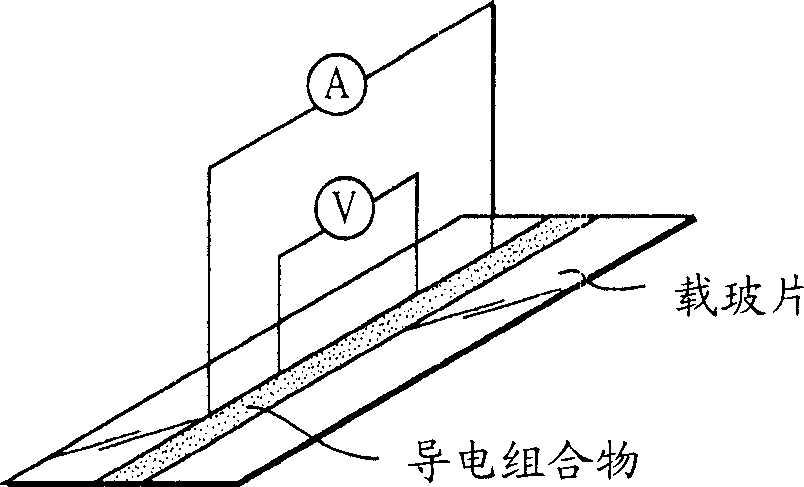
[0042] Contact resistivity test carrier such as Figure 4 As shown, a FR-4 board substrate was included on which was printed an open circuit pattern having 3 mm long metal segments separated by 1 mm horseshoe shaped gaps. The number of connections between the composition and the metal segment is 10. The composition will cure at 175°C for 4 hours.

[0043] By employing multiple metal-adhesive connections in the contact resistance device, the variation in conductivity can be amplified and experimental error minimized. The contact resistance of the entire circuit was measured with a Fluke 45 DualDisplay Multimeter and considered to be the combined resistance obtained by adding the resistivity and the interface resistance between the ends of each metal segment and the test ...

Embodiment 3

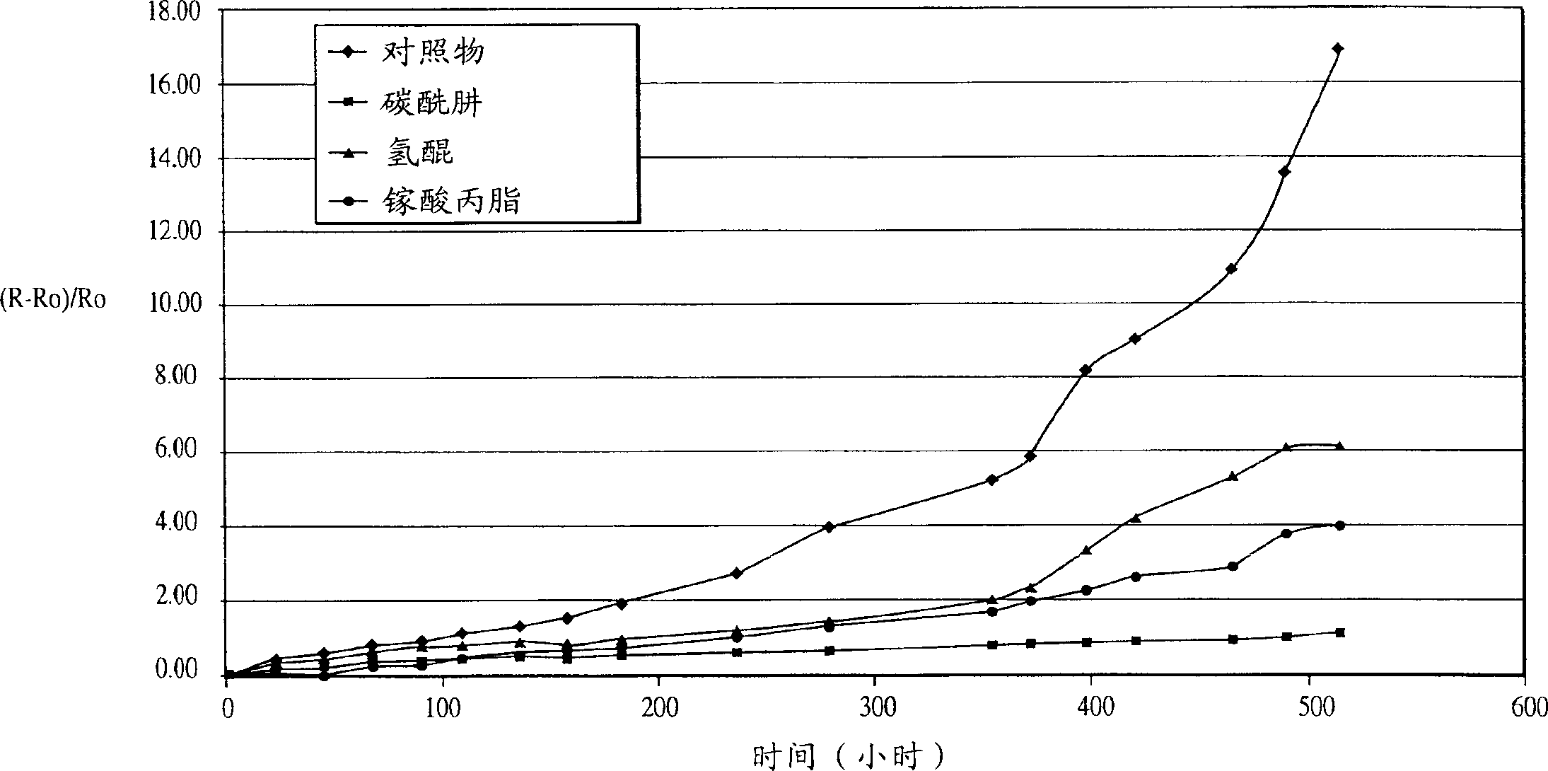
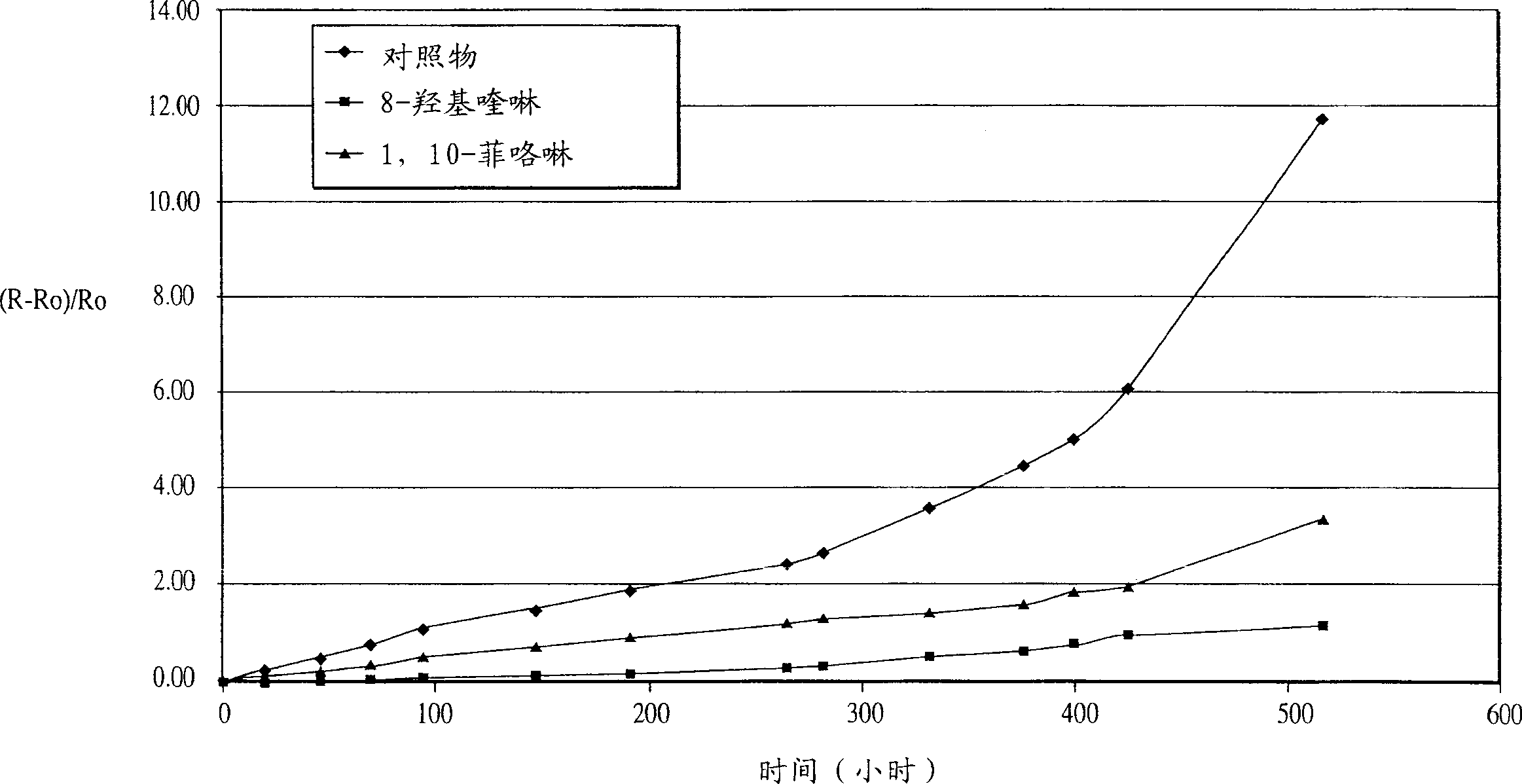
[0049] Example 3: A series of compositions were prepared from composition A in Example 1, doped with different amounts of oxygen scavengers or corrosion inhibitors. As in Example 2, the contact resistivity was measured before and after the treatment under the conditions of 85° C. / 85% relative humidity. The results are shown in Table 4 and show that, except for mercaptobenzothiazole, the presence of oxygen scavengers or corrosion inhibitors are effective in preventing a significant increase in resistivity.

[0050] Composition A


PUM

PropertyMeasurementUnit
widthaaaaaaaaaa

Abstract

A composition for use in microelectronic applications and having improved electrical stability comprising a polymeric resin, a conductive filler, an optional reactive or non-reactive diluent, an optional inert filler, and an oxygen scavenger or corrosion inhibitor agents, or oxygen scavengers and corrosion inhibitors to provide electrical stability. Optionally, the composition may also include a low melting point metal filler component.

Description

field of invention [0001] The present invention relates to compositions suitable for use as conductive or resistive materials in microelectronic devices or semiconductor components to provide electrically stable interconnections. Background of the invention [0002] Compositions of conductive and resistive materials are widely used in the fabrication and assembly of semiconductor components and microelectronic devices. For example, conductive adhesives are used to bond integrated circuit chips to substrates (die attach adhesives) or circuit components to printed circuit boards (surface mount conductive adhesives), and resistive materials are used to form circuit boards planar or embedded resistors on the [0003] In the presence of water, two conductors with different electrochemical potentials form an electrochemical cell. The conductors function as cathode and anode, and the ambient humidity provides the necessary aqueous medium to bridge the an...

Claims


Application Information

Patent Timeline
Patent Type & Authority Applications(China)
IPC IPC(8): C08L101/00C08K3/00C08K3/04C08K3/08C08K3/22C08K3/24C08K3/28C08K3/34C08K3/36C08K5/05C08K5/06C08K5/13C08K5/1515C08K5/1525C08K5/17C08K5/18C08K5/24C08K5/25C08K5/30C08K5/315C08K5/32C08K5/3432C08K5/3437C08K5/3445C08K5/3475C08K5/357C08K5/36C08K5/37C08K5/375C08K5/405C08K5/46C08K5/47C08K5/5398C08K7/06C08L63/00C08L101/02C08L101/06C09J9/02C09J11/04H01B1/12H01B1/20H01B1/22H01B1/24H01L21/52H01L23/498H05K1/09H05K3/32
CPCC09J9/02C09J11/04H01B1/20H01B1/22H01B1/24H01L23/49883H01L2924/0002H05K1/095H05K3/321H01L2924/00
Inventor C·-M·程G·弗雷里克森Y·肖Q·K·童D·卢
Owner NAT STARCH & CHEM INVESTMENT HLDG CORP
Learn More