Array waveguide raster

A technology of arrayed waveguide grating and cylindrical waveguide, which is applied in the coupling of optical waveguide, light guide, optics, etc., can solve the problems that it is difficult to ensure the optical quality of the curved interface of the lens, poor performance consistency, and high production difficulty, so as to improve crosstalk performance, Simple structure and high product yield

Inactive Publication Date: 2003-01-15
FEIHONG OPTICAL NETWORK WUHAN
View PDF3 Cites 8 Cited by
  • Summary
  • Abstract
  • Description
  • Claims
  • Application Information

AI Technical Summary

Problems solved by technology

In the existing planar waveguide process, it is difficult to guarantee the optical quality of the curved surface of the lens and the curved interface of the arrayed waveguide, resulting in disadvantages such as high production difficulty, poor performance consistency, and low yield.

Method used


Image

  • Array waveguide raster
  • Array waveguide raster

Examples


Embodiment Construction

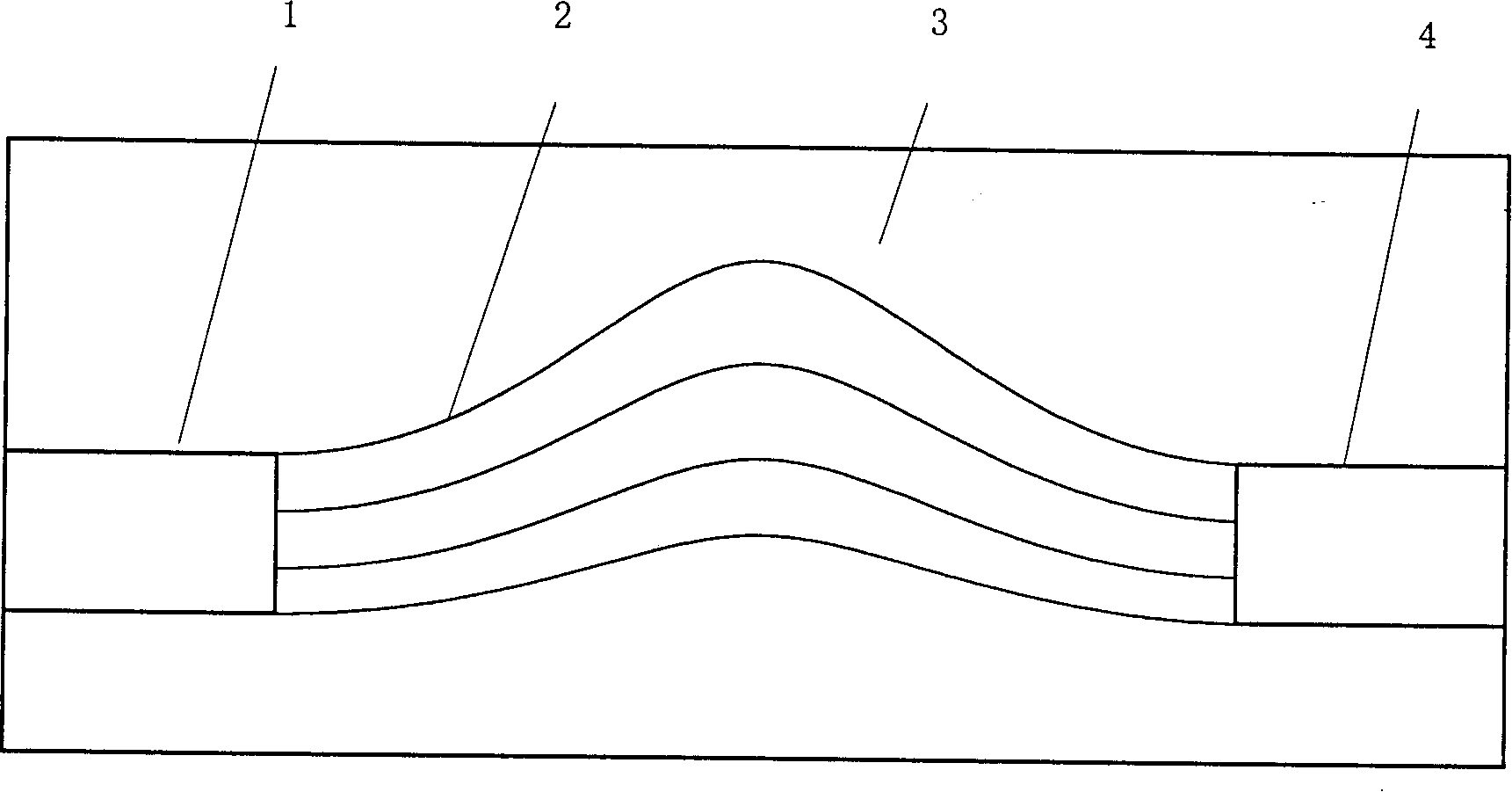
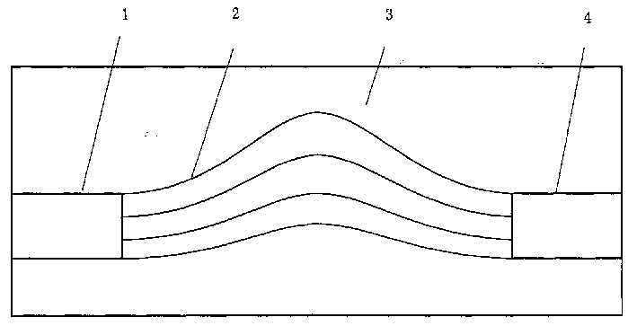
[0013] The arrayed waveguide grating provided by the present invention has a structure as shown in the accompanying drawings: an input coupler 1, a waveguide array 2, and an output coupler 4 are provided. It consists of several cylindrical waveguides.

[0014] The above-mentioned input coupler 1 and output coupler 4 can be composed of graded index slab waveguides, and their incident and outgoing end faces are planes; their refractive index is distributed along the square rate parallel to the surface of the slab substrate 3 and perpendicular to the direction of light propagation , distributed uniformly along the direction perpendicular to the surface of the flat substrate and parallel to the direction of light propagation, forming a self-focusing flat waveguide lens.

[0015] The above-mentioned flat substrate 3 is engraved with V-shaped grooves corresponding to each cylindrical waveguide of the waveguide array 2 one by one. The cylindrical waveguides are positioned in the V-sh...


PUM


Abstract

An array waveguide raster for demultiplexing the multi-wavelength optical signals in dense wave division complexing system structurally features that the input coupler, waveguide array consisting of several cylindrical waveguides and output coupler are sequentially installed on planar substrate. Its method for transmitting optical signsl features that after optical signal is input in said waveguide array, the multi-beam interference takes place to separate the different light wavelengths in space position and output them. Its advantages are high stability, low cost and simple structure.

Description

technical field [0001] The invention relates to the field of optical fiber communication, in particular to an arrayed waveguide grating used for demultiplexing multi-wavelength optical signals in a dense wavelength division multiplexing system. Background technique [0002] In 1988, Smit proposed an arrayed waveguide grating (hereinafter referred to as AWG). After years of hard work, this device is entering the practical stage from laboratory research, and has become one of the most important key devices in dense wavelength division multiplexing (hereinafter referred to as DWDM) optical fiber communication network. Especially in recent years, AWG technology has been a research hotspot in the field of optical communication. [0003] The general structure of AWG includes three parts: input coupler, arrayed waveguide, and output coupler. Among the AWG-related inventions that have been proposed, the output waveguide of the device described in US Patent 6,188,818 is tapered to ...

Claims


Application Information

Patent Timeline
Patent Type & Authority Applications(China)
IPC IPC(8): G02B6/124G02B6/26G02B6/34H04J14/02
Inventor 刘德明鲁平胡必春聂明局
Owner FEIHONG OPTICAL NETWORK WUHAN
Why Eureka
Try Eureka